
Camera structure and assembly method

A camera and lens technology, applied in the field of cameras, can solve the problems of difficult air tightness control, difficult to realize automatic production, focus adjustment, assembly and focus adjustment process, etc. Effect

Pending Publication Date: 2021-07-13
SHENZHEN LONGHORN AUTOMOTIVE ELECTRONICS EQUIPCO
View PDF5 Cites 0 Cited by
  • Summary
  • Abstract
  • Description
  • Claims
  • Application Information

AI Technical Summary

Problems solved by technology

This method has a large number of parts and complicated process
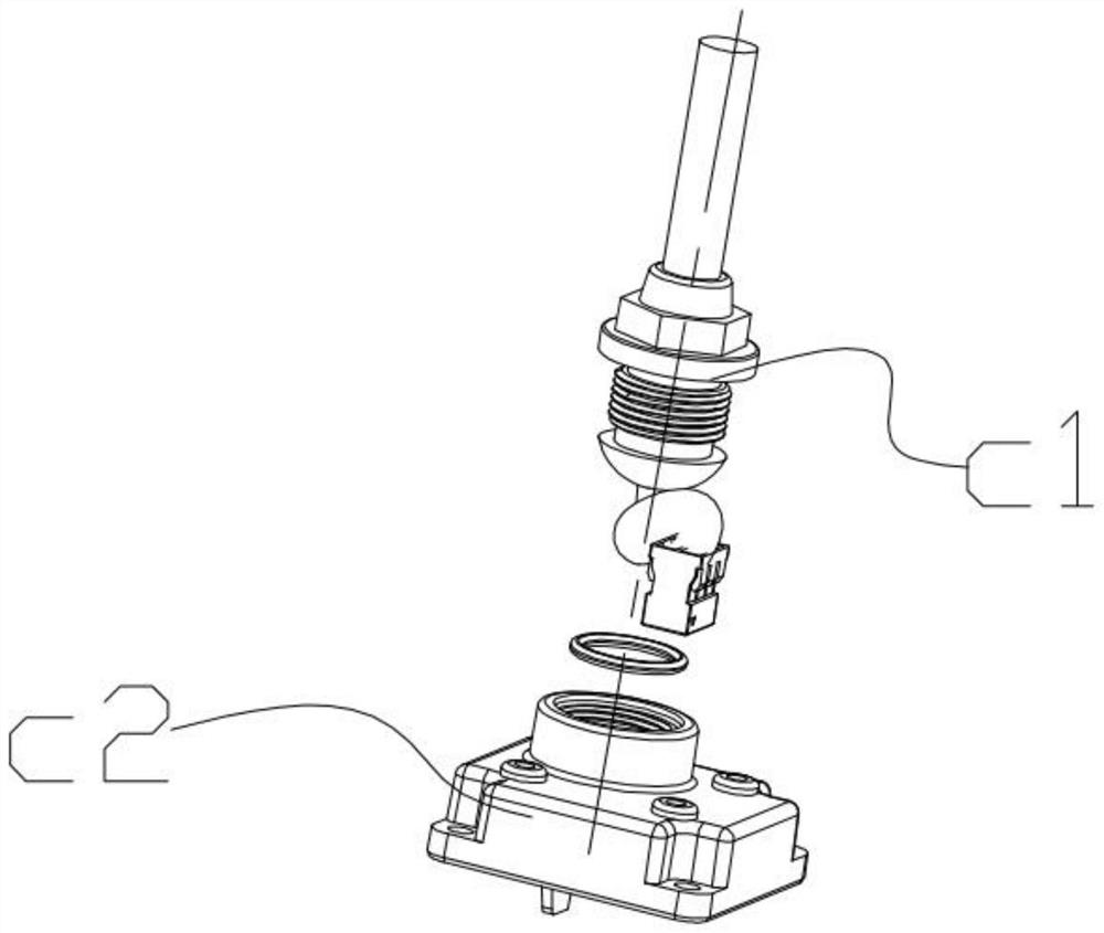
[0006] like image 3 , there is a wire harness c1 at the rear of the camera in the prior art camera, and the wire harness c1 is designed to be assembled with the rear cover c2 in a threaded structure. This method has a large number of parts, complex assembly and difficult air tightness control, which may easily cause water ingress in the camera
When assembling the lens, the existing camera usually adjusts the focus by rotating the lens thread. In this way, the lens can only be rotated and focused vertically along the axis of the lens thread, and other axial focusing cannot be performed, and the assembly and focusing process is cumbersome. , low production capacity, poor product consistency, it is difficult to realize automatic production

Method used


Image

  • Camera structure and assembly method
  • Camera structure and assembly method
  • Camera structure and assembly method

Examples


Embodiment Construction

[0031] The following will clearly and completely describe the technical solutions in the embodiments of the present invention with reference to the accompanying drawings in the embodiments of the present invention. Obviously, the described embodiments are some of the embodiments of the present invention, but not all of them. Based on the embodiments of the present invention, all other embodiments obtained by persons of ordinary skill in the art without making creative efforts belong to the protection scope of the present invention.

[0032] It should also be understood that the terminology used in the description of the present invention is for the purpose of describing particular embodiments only and is not intended to be limiting of the present invention. As used in this specification and the appended claims, the singular forms "a", "an" and "the" are intended to include plural referents unless the context clearly dictates otherwise.

[0033] It should also be further unders...


PUM


Abstract

The invention discloses a camera structure and an assembly method. The camera structure comprises a camera connector and a pin assembly which are connected with each other. The pin assembly comprises a plurality of pin needles, a needle seat and a camera rear cover. The plurality of pin needles are arranged on the needle seat in an array mode and penetrate through the needle seat, and the needle seat and the camera rear cover are integrally formed through secondary injection molding. The plurality of pin needles are accommodated in the camera rear cover, each pin needle comprises an insertion end and a connection end which are connected with each other, the insertion end and the connection end are connected at an inclined angle, the insertion end is electrically connected with the camera connector, and the connection end is electrically connected with an external connector. The camera structure provided by the invention has the advantages of fewer camera parts, more convenient assembly process and the like.

Description

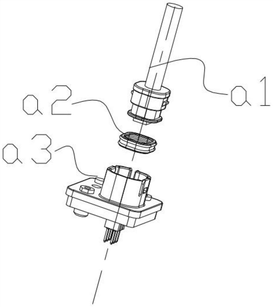
technical field [0001] The invention relates to the field of camera technology, in particular to a camera structure and assembly method. Background technique [0002] Cars are becoming more and more popular in today's society, and traffic accidents have also attracted much attention. Everyone has higher and higher requirements for the safety performance of cars. The driving assistance vision system can greatly reduce the occurrence of collisions and traffic accidents. At present, cars are usually equipped with reversing cameras, and mid-to-high-end models are also equipped with panoramic cameras (front / rear / left / right one each). [0003] There are following problems in prior art camera installation design: [0004] Such as figure 1 In the prior art, there is a wire harness a1 at the rear of the camera head, and the wire harness a1 and the sealing ring a2 are then assembled with the back cover a3 by buckles. This method has many parts and has the problem of airtightness...

Claims


Application Information

Patent Timeline
IPC IPC(8): H04N5/225G03B17/08
CPCG03B17/08H04N23/52H04N23/50
Inventor 罗小平麦福利
Owner SHENZHEN LONGHORN AUTOMOTIVE ELECTRONICS EQUIPCO
Learn More