
Imaging device and electronic apparatus

A technology for camera devices and mounting parts, which is applied to sub-office equipment, televisions, electrical components, etc., can solve the problems of high driving force requirements, high driving force requirements, and complex overall structure of camera devices, and achieve miniaturized design and simplified structure , Improve the effect of focusing range

Active Publication Date: 2021-07-13
VIVO MOBILE COMM CO LTD
View PDF7 Cites 1 Cited by
  • Summary
  • Abstract
  • Description
  • Claims
  • Application Information

AI Technical Summary

Problems solved by technology

[0005] The purpose of this application is to provide an imaging device and electronic equipment, which at least solve the technical problems that the movement of the existing lens module requires a high driving force, and the imaging device requires a high driving force, and the overall structure is complex and inconvenient to design.

Method used


Image

  • Imaging device and electronic apparatus
  • Imaging device and electronic apparatus
  • Imaging device and electronic apparatus

Examples


Embodiment Construction

[0019] Embodiments of the present application will be described in detail below, and examples of the embodiments are shown in the drawings, wherein the same or similar reference numerals denote the same or similar elements or elements having the same or similar functions throughout. The embodiments described below by referring to the figures are exemplary, and are only for explaining the present application, and should not be construed as limiting the present application. Based on the embodiments in this application, all other embodiments obtained by persons of ordinary skill in the art without creative efforts fall within the protection scope of this application.

[0020] For the terms in the specification and claims of the present application, unless otherwise specified, "plurality" means two or more. In addition, "and / or" in the specification and claims represents at least one of the connected objects.

[0021] In the description of the present application, it should be un...


PUM


Abstract

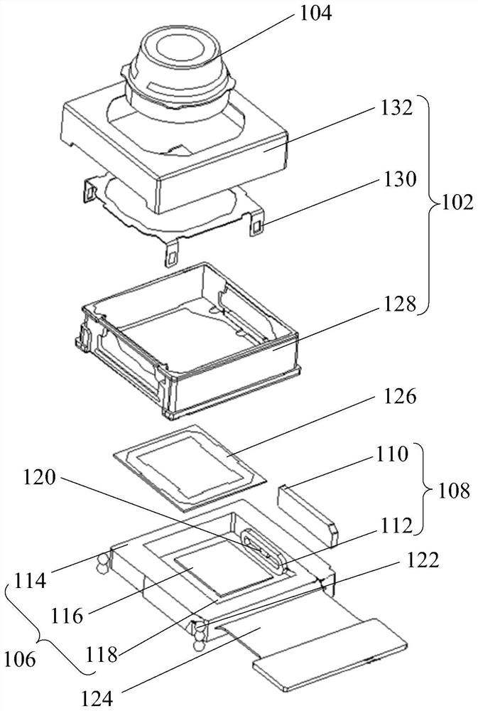
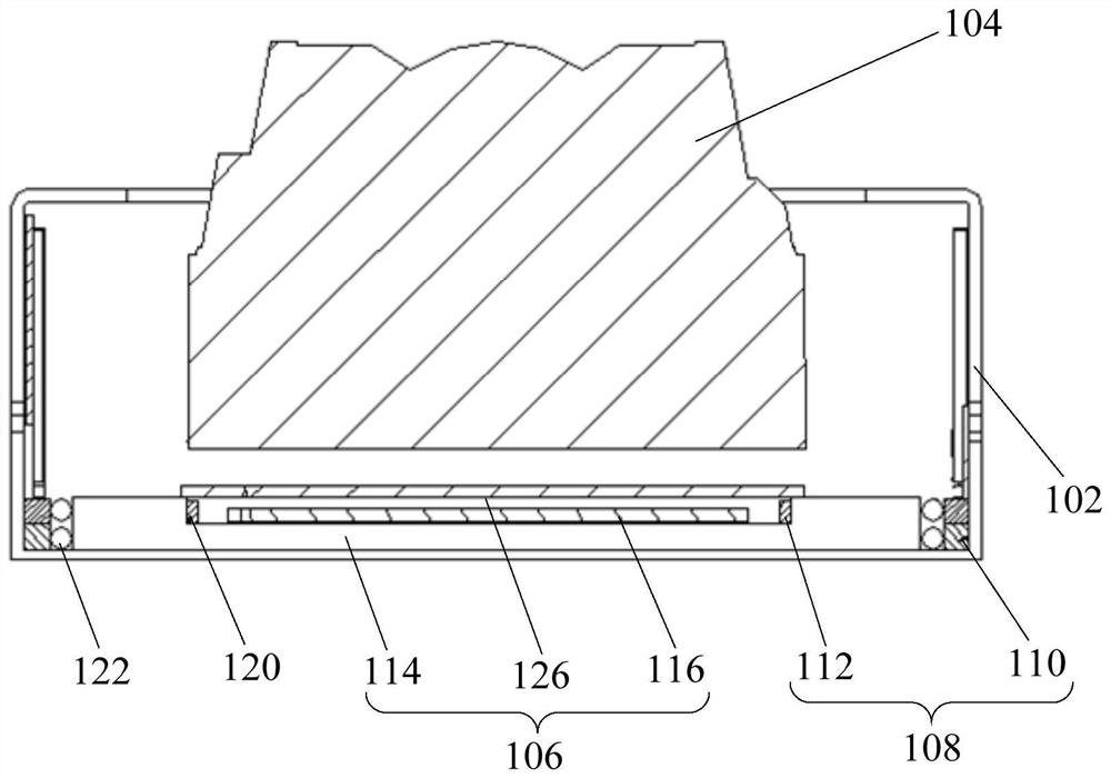
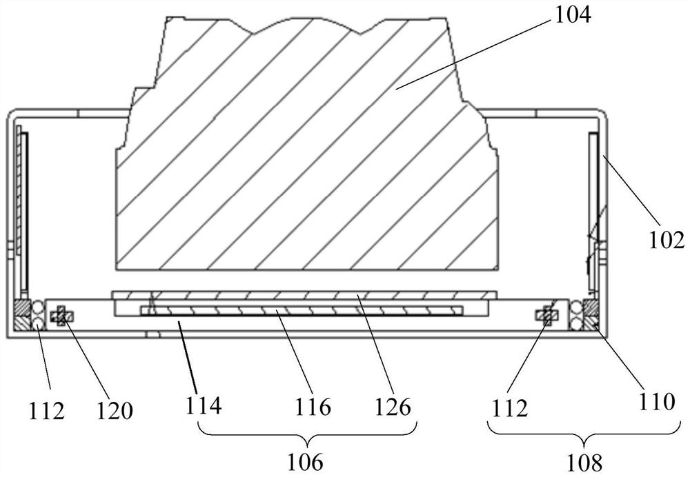
The invention discloses a camera device and electronic equipment. The camera device comprises a shell, a lens module, a photosensitive chip module, a driving part and a rolling part, the photosensitive chip module is arranged in the shell, the lens module is mounted on the shell, and the lens module and the photosensitive chip module are arranged at an interval; wherein the driving part comprises a first driving part and a second driving part which are matched for use, the first driving part is arranged on the shell, the second driving part is arranged in the photosensitive chip module, and the second driving part can be driven by the first driving part to drive the photosensitive chip module to move so as to change the distance from the photosensitive chip module to the lens module; one of the photosensitive chip module and the shell is provided with a containing groove, the rolling piece is located in the containing groove and makes contact with the other one of the installation piece and the shell, and the rolling piece can roll when the photosensitive chip module moves. The driving force of the driving part can be obviously reduced, the miniaturization design of the camera device is realized, and the movement stability of the photosensitive chip module is improved.

Description

technical field [0001] The present application relates to the technical field of electronic equipment, and in particular, to an imaging device and electronic equipment. Background technique [0002] Along with the application of camera device in electronic equipment such as mobile phone more and more widely, become a popular selling point of each mobile phone terminal. The shaking caused by hand-holding or walking when taking pictures and videos makes the image blurred and the image quality is greatly reduced. [0003] In the related art, the camera device adopts an alignment method of driving the movement of the lens module, but the mass of the lens module itself is relatively large, and a relatively large driving force is required during the movement. Future development requires more lens modules, which requires a larger driving force and current design for the camera itself, which is not conducive to the power consumption design of the camera itself. poor. [0004] In ...

Claims


Application Information

Patent Timeline
Patent Type & Authority Applications(China)
IPC IPC(8): H04N5/225H04M1/02
CPCH04M1/0264H04N23/51H04N23/55
Inventor 毛星
Owner VIVO MOBILE COMM CO LTD
Learn More