
Additive machining equipment and machining method
A technology of processing equipment and workbench, which is applied in the direction of additive processing, metal processing equipment, welding equipment, etc., can solve the problems of large welding internal stress, high cost, welding stress deformation, etc., to reduce material waste and shape Uniform and controllable, the effect of improving yield
- Summary
- Abstract
- Description
- Claims
- Application Information
AI Technical Summary
Problems solved by technology
Method used
Image

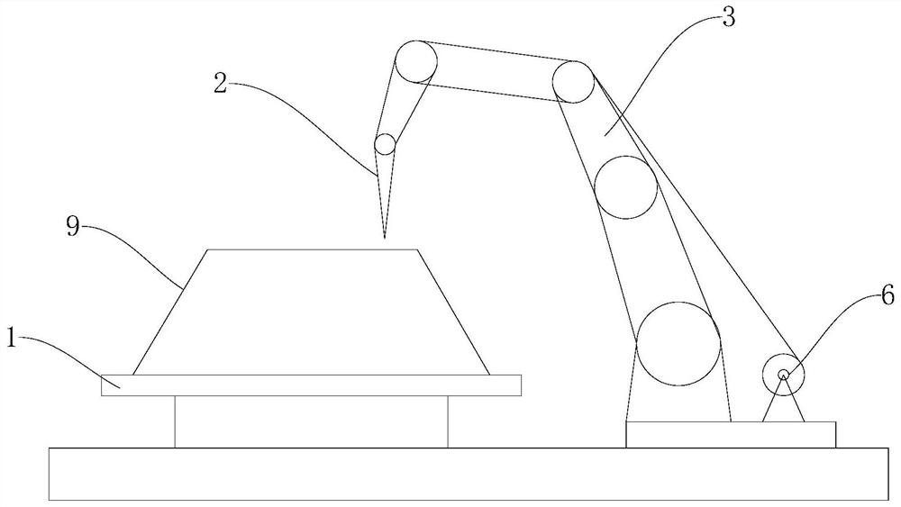
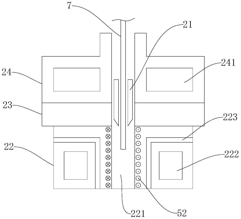
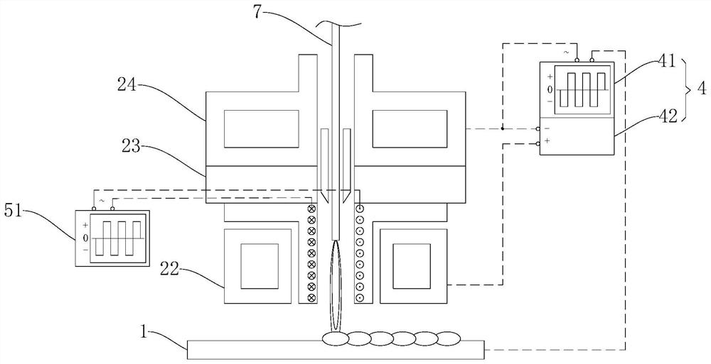
Examples
Embodiment Construction
[0039] In order to make the above objects, features and advantages of the present invention more comprehensible, specific embodiments of the present invention will be described in detail below in conjunction with the accompanying drawings.
[0040] In the description of the present invention, it should be understood that the orientation or positional relationship indicated by the terms "upper", "lower", "front", "rear" etc. is based on the orientation or positional relationship described in the drawings, and is only for It is convenient to describe the present invention and simplify the description, but does not indicate or imply that the device or element referred to must have a specific orientation, be constructed and operate in a specific orientation, and thus should not be construed as limiting the present invention.
[0041] It should be noted that the "connection" mentioned in this embodiment includes detachable connection and non-detachable connection, that is to say, th...
PUM
| Property | Measurement | Unit |
|---|---|---|
| diameter | aaaaa | aaaaa |
Abstract
Description
Claims
Application Information