Anti-corrosion coating spraying equipment for exhaust gas emission pipeline

A technology for spraying equipment and exhaust gas emission, which is applied in the direction of spraying device to achieve the effect of good spraying work, preventing shaking and improving work efficiency

Active Publication Date: 2021-07-23
河北恒泰管道科技有限公司
View PDF8 Cites 11 Cited by
  • Summary
  • Abstract
  • Description
  • Claims
  • Application Information

AI Technical Summary

Problems solved by technology

[0005] In order to overcome the disadvantage of manually painting the outer wall of the exhaust gas discharge pipe with an anti-corrosion paint, the technical problem to be solved by the present invention is to provide an anti-corrosion paint that can automatically spray the outer wall of the exhaust gas discharge pipe, which can save time. Anti-corrosion paint spraying equipment for exhaust pipes that saves labor and improves work efficiency

Method used


Image

  • Anti-corrosion coating spraying equipment for exhaust gas emission pipeline
  • Anti-corrosion coating spraying equipment for exhaust gas emission pipeline
  • Anti-corrosion coating spraying equipment for exhaust gas emission pipeline

Examples


Embodiment 1

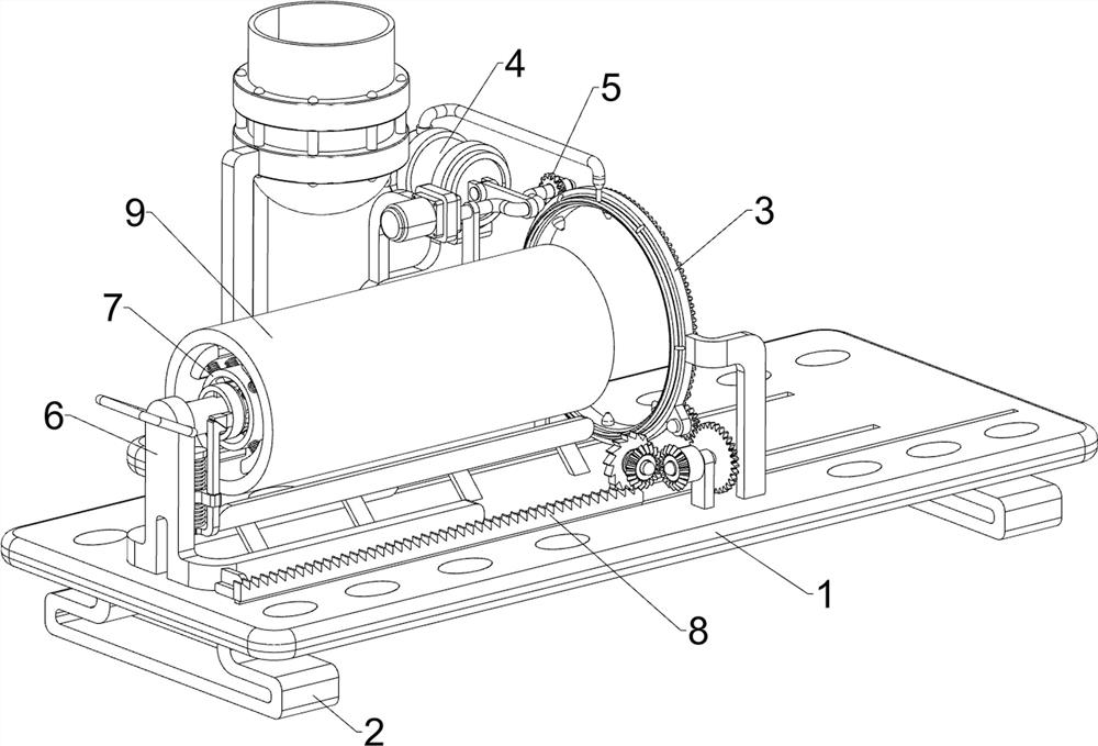
[0029] An anti-corrosion paint spraying equipment for exhaust gas discharge pipes, such as Figure 1-4 As shown, it includes a base plate 1, a support frame 2, a spraying mechanism 3, a feeding mechanism 4 and a rotating mechanism 5, the left and right sides of the bottom of the base plate 1 are connected with a support frame 2, and the base plate 1 is respectively equipped with a spraying mechanism 3, a supply mechanism Feeding mechanism 4 and rotating mechanism 5.

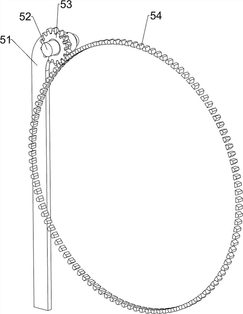
[0030] The spraying mechanism 3 includes a fixed ring frame 31, the first connecting rod 32, a hollow fixed ring 33, a feed joint 34 and a spray frame 35, the right side of the bottom plate 1 top is connected with a fixed ring frame 31, and the left side of the fixed ring frame 31 A plurality of first connecting rods 32 are evenly spaced along the circumferential direction, and a hollow fixing ring 33 is connected between the tail ends of the plurality of first connecting rods 32, and the top of the hollow fixing...

Embodiment 2

[0035] On the basis of Example 1, such as figure 1 and Figure 5 As shown, it also includes a placement frame assembly 6, the placement frame assembly 6 includes a mounting frame 61, a slider 62, a placement bar 63 and a handle 64, two sliders 62 are slidably connected to the top of the bottom plate 1, and the slider 62 is located at the second The front side of the two fixed mounts 44, the tops of the two slide blocks 62 are connected with a mounting frame 61, the mounting frame 61 top is connected with a placement bar 63, and the mounting frame 61 top is connected with a handle 64, and the handle 64 is positioned on the left side of the placement bar 63. side.

[0036] The pipe 9 can be set on the placement rod 63, so that there is no need to manually hold the pipe 9 for spraying, push the handle 64 to the right so that the installation frame 61 moves to the right, and the installation frame 61 moves to the right to drive the placement rod 63 to move to the right. Place ba...

Embodiment 3

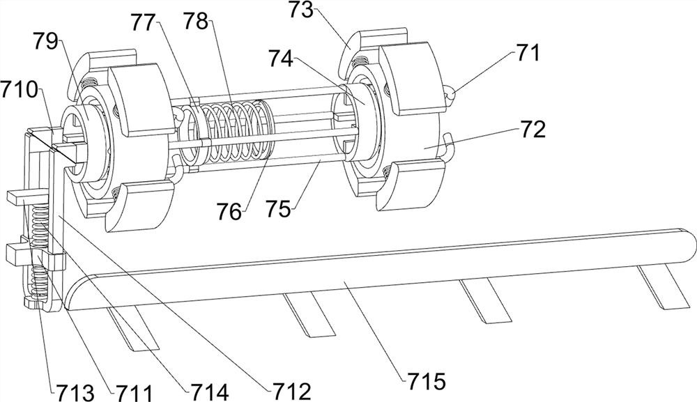
[0038] On the basis of Example 2, such as figure 1 and Figure 6 As shown, it also includes a limit mechanism 7, and the limit mechanism 7 includes a second connecting rod 71, a mounting ring 72, an elastic clamp block 73, a first push ring frame 74, a third connecting rod 75, a limit ring 76, a connection Ring 77, the first spring 78, the second push ring frame 79, fixed wedge block 710, guide block 711, sliding wedge block frame 712, first fixed plate 713, second spring 714 and top plate frame 715, place bar 63 outer walls A plurality of second connecting rods 71 ​​are connected to the left and right sides, and a mounting ring 72 is connected between the second connecting rods 71 ​​on the same side, and a plurality of elastic clips 73 are connected to the mounting ring 72 in a sliding manner evenly spaced along the circumferential direction. , the right side of the outer wall of the placement rod 63 is slidably connected with a first push ring frame 74, and the left side of...


PUM


Abstract

The invention relates to spraying equipment, in particular to anti-corrosion coating spraying equipment for an exhaust gas emission pipeline. According to the anti-corrosion coating spraying equipment for the exhaust gas emission pipeline, anti-corrosion coating can be automatically sprayed to the outer wall of the exhaust gas emission pipeline, time and labor can be saved, and the working efficiency can be improved. The anti-corrosion coating spraying equipment for the exhaust gas emission pipeline comprises a bottom plate, a spraying mechanism, a feeding mechanism and a rotating mechanism, and supporting frames are connected to the two sides of the bottom of the bottom plate; the spraying mechanism is mounted at the top of the bottom plate; the feeding mechanism is mounted at the top of the bottom plate; and the rotating mechanism is mounted at the top of the bottom plate. Through cooperation of the spraying mechanism, the feeding mechanism and the rotating mechanism, an anti-corrosion coating can be uniformly sprayed on the outer wall of the exhaust gas emission pipeline, so that the effects that the anti-corrosion coating can be automatically sprayed on the outer wall of the exhaust gas emission pipeline, time and labor can be saved, and the working efficiency can be improved are achieved.

Description

technical field [0001] The invention relates to a spraying equipment, in particular to a corrosion-resistant paint spraying equipment used for exhaust gas discharge pipes. Background technique [0002] In order to prolong the service life of the exhaust gas discharge pipeline and prevent the exhaust gas discharge pipeline from being corroded by the exhaust gas, it is necessary to paint the outer wall of the exhaust gas discharge pipeline with anti-corrosion paint. When painting, pour the anti-corrosion paint on the outer wall of the exhaust gas discharge pipe, and then manually use a brush to paint the anti-corrosion paint on the outer wall of the exhaust gas discharge pipe evenly. This method takes more time and energy, and is more efficient. Low, long hours of work people are prone to fatigue. [0003] Therefore, it is necessary to design an anti-corrosion paint spraying equipment for exhaust gas discharge pipes that can automatically spray anti-corrosion paint on the out...

Claims


Application Information

Patent Timeline
Patent Type & Authority Applications(China)
IPC IPC(8): B05B13/02B05B13/04
CPCB05B13/0214B05B13/0278B05B13/0426Y02P70/10
Inventor 涂品云
Owner 河北恒泰管道科技有限公司
Why Eureka
Try Eureka