Centrifugal casting molten iron feeding device
A feeding device and centrifugal casting technology, which is applied in casting equipment, casting molten material containers, equipment for supplying molten metal, etc., can solve the problems of affecting casting quality, unable to remove molten iron oxidized slag, difficult measurement of molten iron, etc., to achieve guaranteed The effect of casting volume
- Summary
- Abstract
- Description
- Claims
- Application Information
AI Technical Summary
Problems solved by technology
Method used
Image

Examples
Embodiment 1
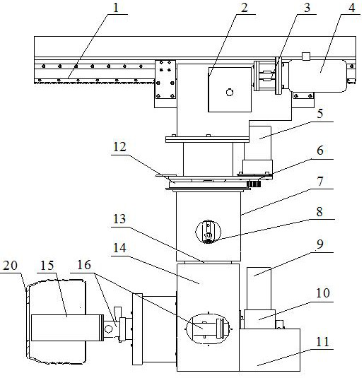
[0025] The structure of this embodiment is suitable for casting the gray cast iron friction layer on the inner wall of the rotating brake drum shell during centrifugal casting of the bimetallic brake drum.
[0026] Such as figure 1 As shown, the basic structure of this embodiment is to set a horizontal sliding device on a suspension rail, the sliding device is provided with a linear reciprocating movement mechanism, a rotary reciprocating swing mechanism is arranged on the linear reciprocating movement mechanism, and an overturning device is arranged on the rotary reciprocating swing mechanism. Set the molten iron ladle on the turning device. Therefore, the molten iron ladle can be overturned, rotated and reciprocated, and can also be reciprocated in a straight line to realize the multi-dimensional movement of the molten iron ladle. At the same time, a metering device is also installed on the above-mentioned device to measure the weight of molten iron to realize positioning,...
Embodiment 2
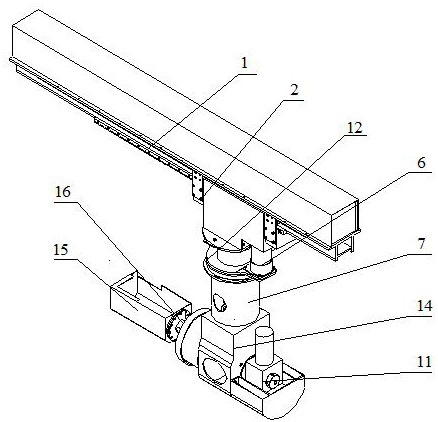
[0040] Such as Figure 4 As shown, this embodiment is basically the same as Embodiment 1, and the different parts of the structure no longer use the suspension rail structure, but the ground rail structure. That is, the ground rail is set on the ground or the platform, the sliding track 1 is arranged on the ground rail, the sliding drive motor 4 and the sliding deceleration device 3 are arranged on the sliding chassis 2, the metering box 7 is arranged on the sliding chassis 2, and the tension pressure sensor is arranged in the metering box 7 8. The upper end of metering 7 is provided with turning over cabinet 14 again. That is to say, the present embodiment removes the rotary reciprocating swing mechanism of the first embodiment, and other structures and positions are just opposite to those of the first embodiment, and the turning case 14 is arranged at the top of the device. The upper side of the molten iron ladle 15 can be directly docked with the molten iron heat preserva...
Embodiment 3
[0043] This embodiment is also a structural change on the basis of Embodiment 1. This embodiment also adopts the suspension rail structure, removes the rotary reciprocating swing mechanism, and directly connects to the flipping cabinet 14 through the metering box 7 at the lower end of the sliding cabinet 2 . Setting the overturning shaft 16 to a sufficient axial length can avoid the space position conflict between the suspension rail and the molten iron insulation bag, but due to the extension of the overturning shaft 16, a corresponding counterweight body needs to be equipped at the same time.
PUM
 Abstract
Description
Claims
Application Information
 - R&D
- Intellectual Property
- Life Sciences
- Materials
- Tech Scout
- Unparalleled Data Quality
- Higher Quality Content
- 60% Fewer Hallucinations
Browse by: Latest US Patents, China's latest patents, Technical Efficacy Thesaurus, Application Domain, Technology Topic, Popular Technical Reports.
© 2025 PatSnap. All rights reserved.Legal|Privacy policy|Modern Slavery Act Transparency Statement|Sitemap|About US| Contact US: help@patsnap.com