Tread pattern of passenger car

A passenger car tire and tread pattern technology, which is applied to tire tread/tread pattern, vehicle parts, tire parts, etc., can solve the problem of less tread pattern design, avoid tread stress concentration, and reduce rolling resistance , The effect of improving the rigidity of the tread

Active Publication Date: 2021-07-23
JIANGSU UNIV
View PDF8 Cites 0 Cited by
  • Summary
  • Abstract
  • Description
  • Claims
  • Application Information

AI Technical Summary

Problems solved by technology

However, due to the varying degrees of incompatibility between rolling resistance and grip performance, there are few tread pattern designs that can synergistically improve tire performance.

Method used


Image

  • Tread pattern of passenger car
  • Tread pattern of passenger car

Examples


Embodiment 1

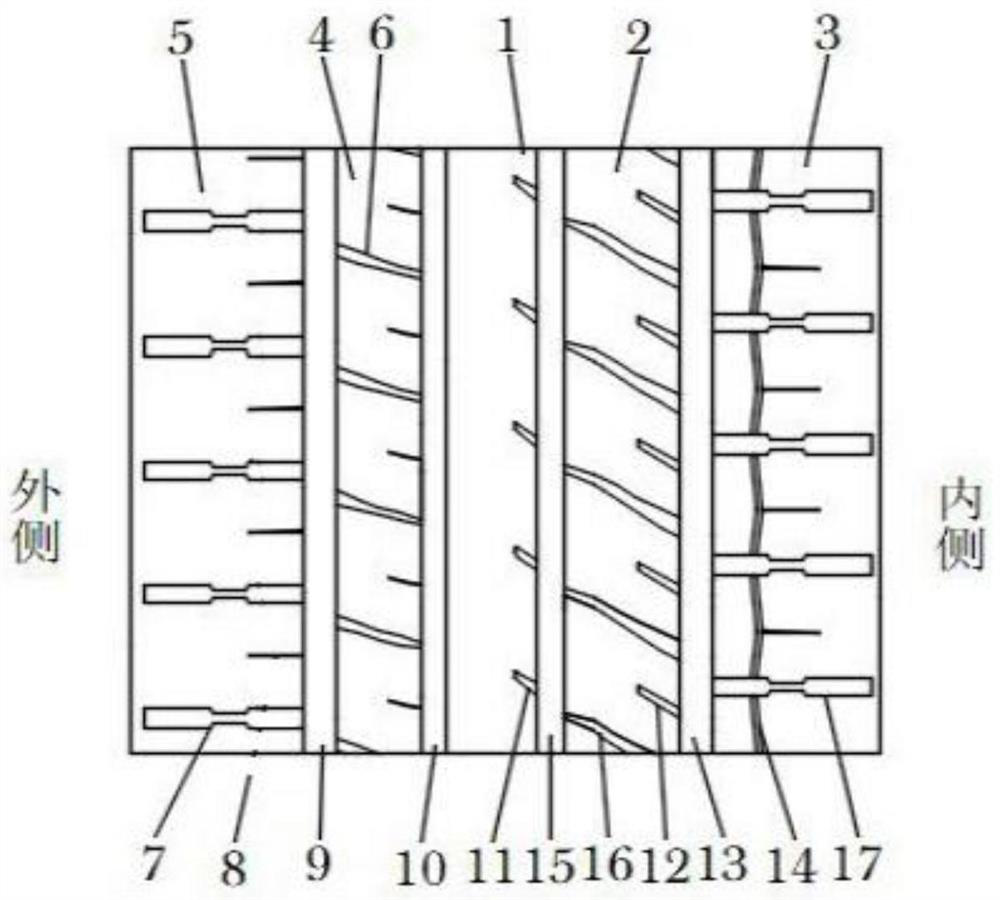
[0026] like figure 1 As shown, the passenger car tread pattern of the present invention includes a central pattern block 1 located in the transverse middle of the tread, an outer transition zone pattern block 4 located at the central pattern block 1 towards the outer lateral edge of the tire, and a pattern block located in the outer transition zone 4 the outer shoulder area block 5 at the lateral edge, the inner transition area block 2 located at the lateral edge of the central block 1 towards the inner side of the tire, and the inner shoulder area block 3 located at the lateral edge of the inner transition area block 2 .

[0027] A central outer longitudinal pattern groove 10 is arranged between the central pattern block 1 and the outer transition region pattern block 4, and the central outer longitudinal pattern groove 10 is arranged around the tire ring; the connection between the central pattern block 1 and the inner transition region pattern block 2 There are central inne...

Embodiment 2

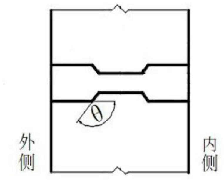
[0037] Excluding the length of the narrow groove segment, the length from the center of the narrow groove segment in the middle of the concave transverse groove A7 to the inner edge of the pattern block 5 in the outer tire shoulder area, and the length from the center of the narrow groove segment in the middle of the concave transverse groove B to the inner tire shoulder area The length of the inner edge of the pattern block 3 is different, and the other structures of the tire tread are the same, wherein the length of the narrow groove segment is 1 / 4 of the width of the pattern block 3 in the inner shoulder area or the width of the pattern block 5 in the outer shoulder area; The length from the center of the narrow groove segment in the middle of the concave transverse groove A7 to the inner edge of the pattern block 5 in the outer tire shoulder area is 1 / 2 of the width of the pattern block 5 in the outer tire shoulder area; the center of the narrow groove segment in the middle ...


PUM


Abstract

The invention provides a passenger car tread pattern. The passenger car tread pattern comprises a central pattern block, an outer transition area pattern block, an outer tire shoulder area pattern block, an inner transition area pattern block and an inner tire shoulder area pattern block; central outer side longitudinal pattern grooves are formed between the central pattern blocks and the outer transition area pattern blocks, and auxiliary transverse pattern grooves A are formed in the outer transition area pattern blocks; concave transverse grooves A are formed in the outer tire shoulder area pattern blocks; auxiliary transverse pattern grooves B are formed in the inner transition area pattern blocks; inner transition area transverse pattern grooves are formed in the inner transition area pattern blocks; concave transverse grooves B are formed in the inner tube shoulder area pattern blocks; inner tube shoulder auxiliary longitudinal pattern grooves are formed in the inner tube shoulder area pattern blocks, accumulated water in a grounding area in the running process of the tire can be effectively removed, and through the pattern blocks with different sizes in the transition area and the tire shoulder area and the staggered arrangement layout, the cooperative improvement of the rolling resistance and the gripping performance of the tire is achieved.

Description

technical field [0001] The invention relates to the technical field of vehicle tires, in particular to a passenger car tread pattern. Background technique [0002] In recent years, the tire labeling laws issued by the European Union and other countries have put forward higher requirements on the rolling resistance and grip performance of tires. However, nearly half of the tires in my country still fail to meet the EU's second-stage standards. my country began to implement the "Green Tire Technical Specifications" in 2014 in response to tire labeling laws issued by countries around the world. The "Green Tire Technical Specifications" pointed out that green tires are energy-saving, environmentally friendly and safe radial tire products, which have low rolling resistance, Outstanding product features such as fuel consumption, excellent handling stability, and shorter braking distance. Studies have shown that reducing the rolling resistance of tires by 15% to 30% can save fuel c...

Claims


Application Information

Patent Timeline
IPC IPC(8): B60C11/12B60C11/13B60C11/01B60C11/03
CPCB60C11/1281B60C11/1204B60C11/13B60C11/01B60C11/0304B60C2011/1286B60C2011/013Y02T10/86
Inventor 梁晨刘浩潘甦昊柏林喻康颖祁勐
Owner JIANGSU UNIV
Why Eureka
Try Eureka