
Patsnap Eureka
For R&D, Patsnap Eureka makes reading and utilizing patents & technical documents easy.
Patsnap Eureka AIR
Designed for self-driven R&D workflows. Generate viable solutions, solve complex R&D challenges, empower your innovation with AI.

Patsnap Eureka Materials
Designed for material experts only. Revolutionize your material R&D, from search, analyze, to developing new materials.

TechResearch
Generate reliable direction feasibility study reports for your R&D in just a few steps.

TechSeek
Discover and master advanced knowledge NOW. Basics, ideas, possibilities, all at once.

TechMind
As an expert in R&D Theories, TechMind can generates customized viable solutions instantly.

TechRisk
Analyze your overall solution with one click, know your potential R&D risks in advance.

TechMonitor
Get weekly tech updates, stay abreast of the latest tech innovations and key insights.
Multi-locking mechanism applied to trolley operation
A technology of locking mechanism and running mechanism, which is applied in the directions of walking mechanism, transportation and packaging, load hanging components, etc., can solve the problems of poor stability, inconvenient adjustment of the position of the trolley, and complicated operation, and achieve high safety and easy adjustment of the position of the trolley. , the effect of convenient operation
- Summary
- Abstract
- Description
- Claims
- Application Information
AI Technical Summary
Problems solved by technology
Method used
Image

Examples
Embodiment 1
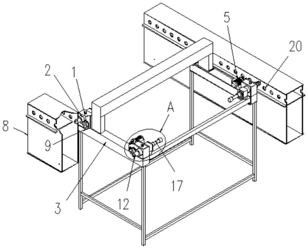
[0023] Example 1: See Figure 1-2 , the present invention provides a technical solution: a multiple locking mechanism for trolley operation, including a running locking device and a trolley frame 3; the running locking device is installed at the top four corners of the trolley frame 3, and the running locking device Including running mechanism 1, locking mechanism 2 and fixed block 11; running mechanism 1 is used to adjust the position of the trolley when the trolley is empty, running mechanism 1 can form a wheel-rail kinematic pair with the track 9 on the fixed beam 8, and locking mechanism 2 is used for trolley The locking position is used; the fixed block 11 is fixed on the top of the trolley frame 3; the top of the fixed block 11 is provided with a locking hole 18, and the locking hole 18 is internally threaded with a fastening screw 10 for connecting the pin shaft 12 with the fixed beam After the pin hole 20 on the 8 is inserted, the pin shaft 12 is locked again, and the ...
Embodiment 2
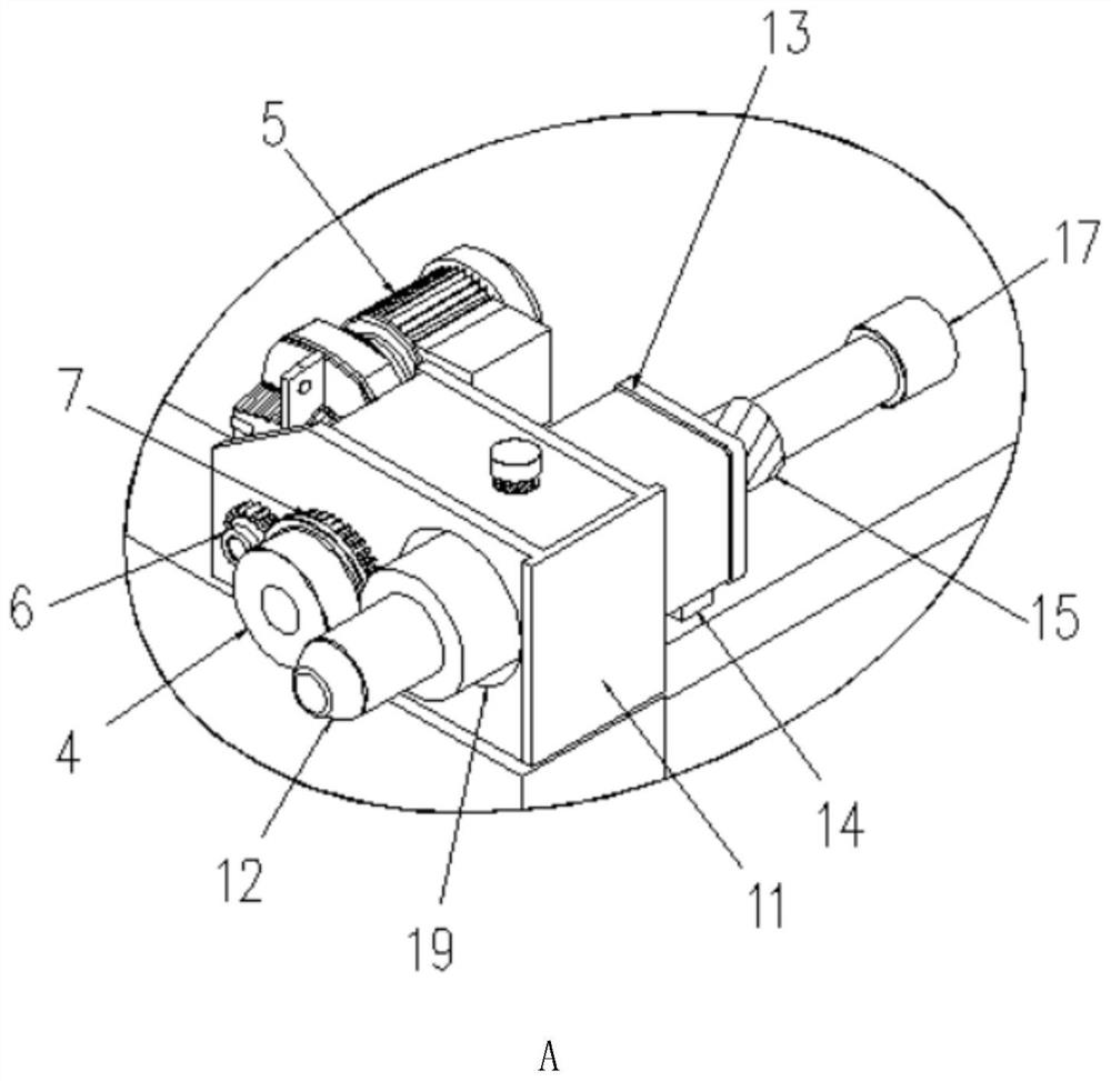
[0024] Example 2: See image 3 , this embodiment is further on the basis of Embodiment 1, the running mechanism 1 includes a wheel 4 and a drive motor 5; the drive motor 5 is installed inside the fixed block 11, and the output end of the drive motor 5 passes through the fixed block 11 and is fixedly connected with the driving gear 6; the wheel 4 is rotatably mounted on the outside of the fixed block 11, the surface of the wheel 4 is fixedly sleeved with the driven gear 7, and the driving gear 6 is engaged with the driven gear 7.
[0025] When the trolley adjusts its position with no load, start the driving motor 5, the output end of the driving motor 5 drives the driving gear 6 to rotate, the driving gear 6 drives the wheel 4 to rotate through the driven gear 7, and the wheel 4 forms a wheel rail with the track 9 on the fixed beam 8 The kinematic pair, and then the trolley can be moved to adjust the position, and the operation is convenient.
Embodiment 3
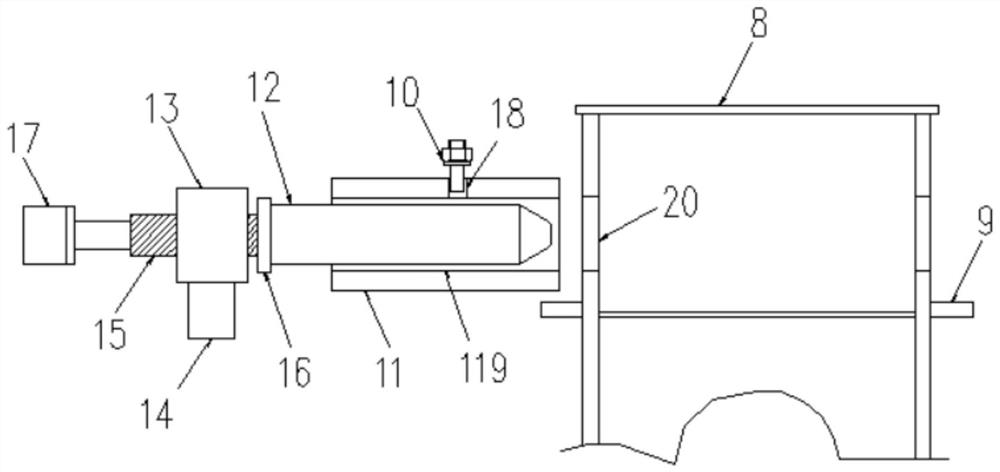
[0026] Example 3: See Figure 4 , this embodiment is further on the basis of Embodiment 1, the locking mechanism 2 includes a pin shaft 12 and a threaded pipe 13; the pin shaft 12 is set through the fixing block 11, and the threaded pipe 13 is located at the fixing block 11 away from the fixed beam 8, and the threaded pipe 13 is fixedly connected to the top of the trolley frame 3 through the fixed rod 14, the threaded pipe 13 runs through a threaded rod 15, and the threaded pipe 15 and the pin shaft 12 are connected by a mounting plate 16, and the mounting plate One side of the screw rod 16 is fixedly connected with the screw shaft 15, and the other side of the mounting plate 16 is connected with the pin shaft 12 in rotation; the end of the screw shaft 15 away from the pin shaft 12 is fixedly connected with a rotating handle 17.
[0027] When the trolley is locked, the trolley moves to adjust the position under the action of the operating mechanism 1. After adjustment, the scr...
PUM
 Abstract
Description
Claims
Application Information
 - R&D Engineer
- R&D Manager
- IP Professional
- Industry Leading Data Capabilities
- Powerful AI technology
- Patent DNA Extraction
Browse by: Latest US Patents, China's latest patents, Technical Efficacy Thesaurus, Application Domain, Technology Topic, Popular Technical Reports.
© 2024 PatSnap. All rights reserved.Legal|Privacy policy|Modern Slavery Act Transparency Statement|Sitemap|About US| Contact US: help@patsnap.com