Smart plug integrated sensor system

A technology of sensors and data transmission systems, applied in the field of smart plug systems integrating sensors, capable of solving limited and other problems

Pending Publication Date: 2021-07-23
SCHLUMBERGER TECH LTD BV
View PDF8 Cites 0 Cited by
  • Summary
  • Abstract
  • Description
  • Claims
  • Application Information

AI Technical Summary

Problems solved by technology

However, the travel of dummy frac plugs is often very limited in terms of what they can achieve

Method used


Image

  • Smart plug integrated sensor system
  • Smart plug integrated sensor system
  • Smart plug integrated sensor system

Examples


Embodiment Construction

[0018] In the following description, numerous details are set forth in order to provide an understanding of some illustrative embodiments of the present disclosure. However, it will be understood by those of ordinary skill in the art that the systems and / or methods may be practiced without these details and that various changes or modifications may be made to the described embodiments.

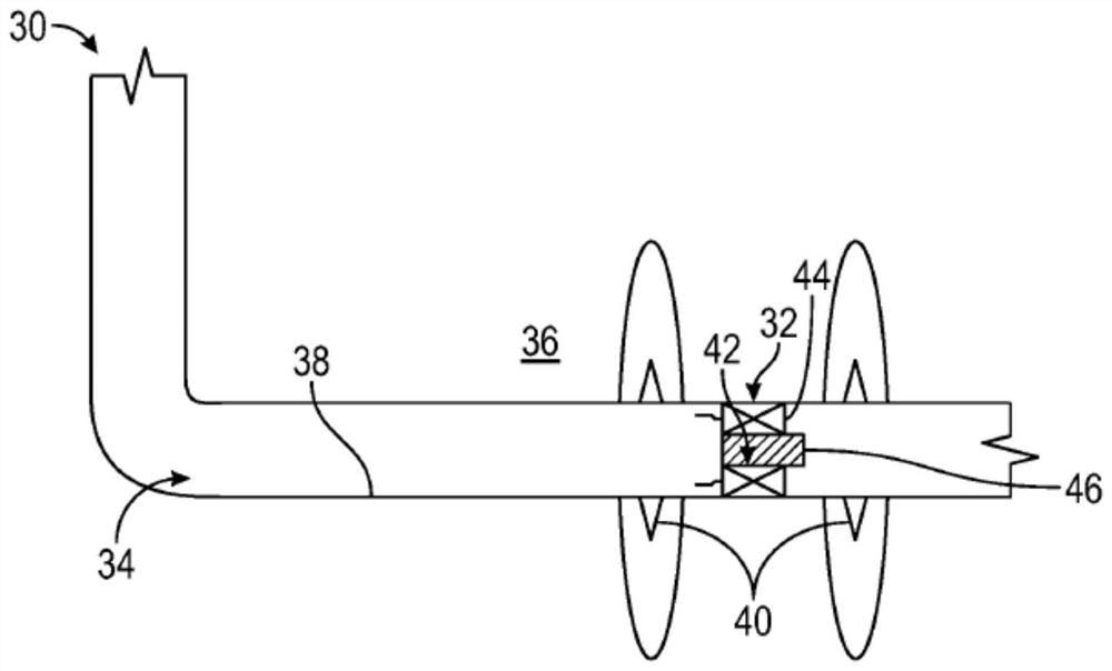
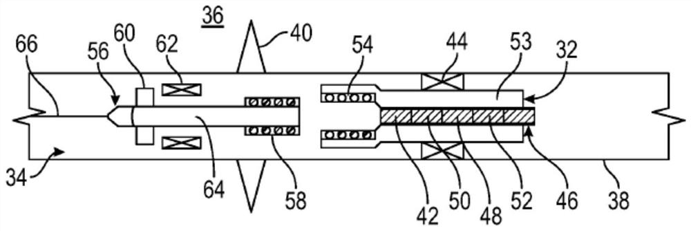
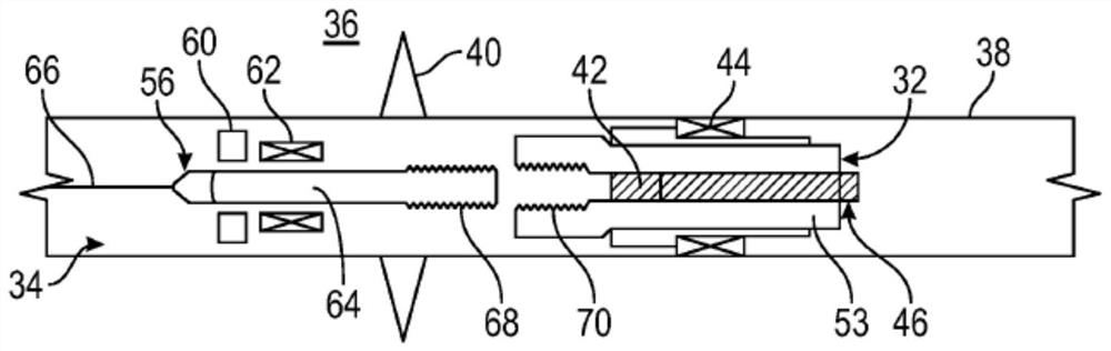
[0019] The disclosure herein relates generally to a system and method for obtaining information (eg, temperature data, pressure data, or other desired data) related to a fracturing operation. According to one embodiment, the frac plug is provided with electronics for obtaining desired information related to the frac operation. For example, a frac plug may consist of electronic sensors, digital storage, and a power supply and / or other electrical related equipment. Depending on the application, the frac plug may be a composite frac plug, a degradable frac plug, or other suitable frac plugs. Re...


PUM


Abstract

A technique facilitates collecting data, related to a fracturing, run-in-hole, or pull-out-of hole operation. A frac plug is provided with electronics for obtaining the desired information related to the operation. For example, the frac plug may be constructed with electronic sensors, a digital storage device, and a power supply or other power related equipment. Depending on the application, the frac plug may be a composite frac plug, degradable frac plug, dummy frac plug, or other suitable frac plug. Retrieval of the information obtained may be done via coupling with an associated device, e.g. inductive or physical coupling, by utilizing a broadcast transmitter / receiver, by physical retrieval of the storage device, or by physical retrieval of the dummy frac plug.

Description

[0001] Cross References to Related Applications [0002] This document is based on and claims priority from U.S. Provisional Application Serial No. 62 / 781,427, filed December 18, 2018, the entire contents of which are incorporated herein by reference. Background technique [0003] Following the discovery of a desired subterranean resource, such as oil, natural gas, or other desired subterranean resource, drilling and fracturing operations are sometimes performed to facilitate access to the subterranean resource. During a fracturing operation, a frac plug may be deployed downhole and positioned at a desired location along the wellbore. Frac plugs allow pressure to be applied downhole and perforated into the surrounding formation, thereby fracturing the formation. To obtain information about the fracturing operation, relatively expensive external instrumentation is deployed and corresponding control lines are laid on the outside of the casing. However, external instrumentation...

Claims


Application Information

Patent Timeline
Patent Type & Authority Applications(China)
IPC IPC(8): E21B33/12E21B43/26E21B47/06E21B47/12
CPCE21B47/06E21B43/26E21B33/12E21B47/13E21B47/07E21B47/01
Inventor I·阿维莱斯J·惠特西特W·诺丽德S·雅塞克R·M·格雷厄姆L·阿尔泰拉克B·潘迪西A·谢雷尔H·涂H·哈拉特
Owner SCHLUMBERGER TECH LTD BV
Why Eureka
Try Eureka