Switchable pi shape antenna

An antenna and wireless signal technology, applied in the direction of antenna, resonant antenna, antenna parts, etc., can solve the problem that T-shaped antenna is not very suitable

Active Publication Date: 2017-05-10
HUAWEI TECH CO LTD
View PDF15 Cites 0 Cited by
  • Summary
  • Abstract
  • Description
  • Claims
  • Application Information

AI Technical Summary

Problems solved by technology

Conventional T-antennas are limited in frequency band covera

Method used


Image

  • Switchable pi shape antenna
  • Switchable pi shape antenna
  • Switchable pi shape antenna

Examples


Embodiment Construction

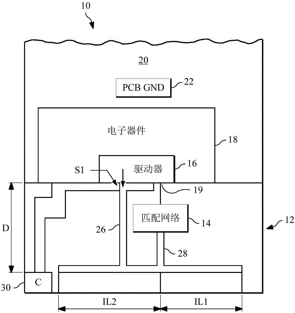
[0020] The present invention provides a mobile device comprising a low-profile pi-shaped antenna comprising a switchable design for covering multiple common 4G LTE frequency bands from B17 to B7 as well as high frequency band B41. A π-shaped antenna is defined as an antenna having at least two arms, each coupled to a radiating element and together forming the shape of the Greek symbol π.

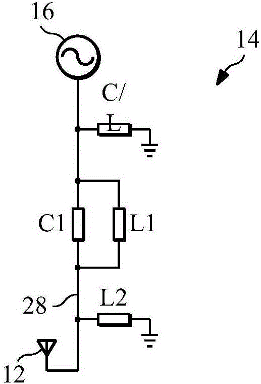
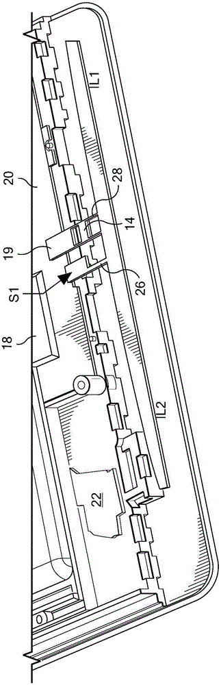
[0021] refer to figure 1 , shows a mobile device 10 comprising a switchable π-shaped antenna 12 with three arms: IL1, IL2 and coupling arm S1. The coupling arm S1 in combination with another component, such as a connector as will be described below, is advantageously used to provide resonance to generate the π-row antenna 12 in the high frequency band, thereby expanding the bandwidth of the antenna on the mobile device 10 . Additionally, an impedance matching network 14 is used to impedance match the antenna 12 to a radio frequency (RF) driver circuit 16 forming part of the device electroni...


PUM


Abstract

A mobile device (10) including a housing having a distal end, and electronics (18) disposed in the housing configured to operate the mobile device (10). A connector (30) is coupled to the electronics (18), and a Pi-shaped antenna (12) has a coupling coupled to the connector (30) to create a resonance using the connector (30). The Pi-shaped antenna (12) and the connector (30) are configured to wirelessly send and receive the wireless signals. An impedance matching network (14) matches the impedance of the electronics (18) to the Pi-shaped antenna (12). The impedance matching network (14) is switchable by the electronics (18) and is configured to match an impedance of the electronics (18) to the Pi-shaped antenna (12) in at least two states, over multiple RF bands.

Description

[0001] Related Applications Cross Application [0002] This application claims priority to prior application of U.S. Nonprovisional Patent Application No. 14274474, filed May 9, 2014, entitled "SWITCHABLE PISHAPE ANTENNA," the entire contents of which prior application Incorporated herein by reference. technical field [0003] The present invention is directed to antennas, particularly low profile antennas used to cover ubiquitous frequency bands in advanced mobile devices including smartphones. Background technique [0004] Wireless mobile devices, including smartphones, require low-profile antennas to meet the required product form factors. The available inner dimensions (ID) of these devices are limited by a number of factors including other component layout designs. [0005] Conventional T-shaped antennas are commonly used in smartphones, where the T-shaped antenna is suitable for covering third generation (3G) frequency bands without the presence of a USB connector in...

Claims


Application Information

Patent Timeline
IPC IPC(8): H01Q1/24H01Q5/335H01Q5/371
CPCH01Q1/243H01Q5/371H01Q1/44H01Q5/378H01Q5/335H01Q9/04H01Q1/38H01Q1/50H04L25/02H04L25/0278H04W72/0453H01Q5/00
Inventor 刘宏伟马宁
Owner HUAWEI TECH CO LTD
Why Eureka
Try Eureka