
Plug connection

a technology of plug-in connection and connection, which is applied in the direction of coupling contact members, coupling device connections, transportation and packaging, etc., can solve the problems of high data rate transmission rates of in-connector contacts, lack of robustness for use in train couplings of this kind, and high number of plug-in cycles required by railway operators, etc., to achieve less abrasion, less wear, and sufficient corrosion protection

Active Publication Date: 2020-01-21
HARTING ELECTRIC GMBH & CO KG
View PDF12 Cites 0 Cited by
  • Summary
  • Abstract
  • Description
  • Claims
  • Application Information

AI Technical Summary

Benefits of technology

The patent describes a connector design that ensures a high number of plug-in cycles and reduces wear and tear on the contact surfaces. This is achieved by using dielectrics that prevent damage to the contact surfaces during coupling. The impedance of the connector can also be adjusted by adjusting the distances between the differential pairs of contacts, which simplifies the calculation and simulation of the impedance. The use of cylindrical contacts further simplifies the analysis and design of the connector.

Problems solved by technology

A fundamental problem is that conventional plug-in connector contacts which are suitable for transmitting high data rates of this kind, that is to say of, for example, 1 GHz and more, generally lack the requisite robustness for use in train couplings of this kind.
Furthermore, a particularly high number of plug-in cycles is required by railway operators specifically for train couplings, it being possible to meet this requirement only with great difficulty using contacts of said kind.
All of these apparatuses have the disadvantage that production thereof is complicated and associated with corresponding costs.
The wireless connections are generally even more complicated since they usually require a modulation / demodulation devices and associated antennas.

Method used


Image

  • Plug connection
  • Plug connection
  • Plug connection

Examples


Embodiment Construction

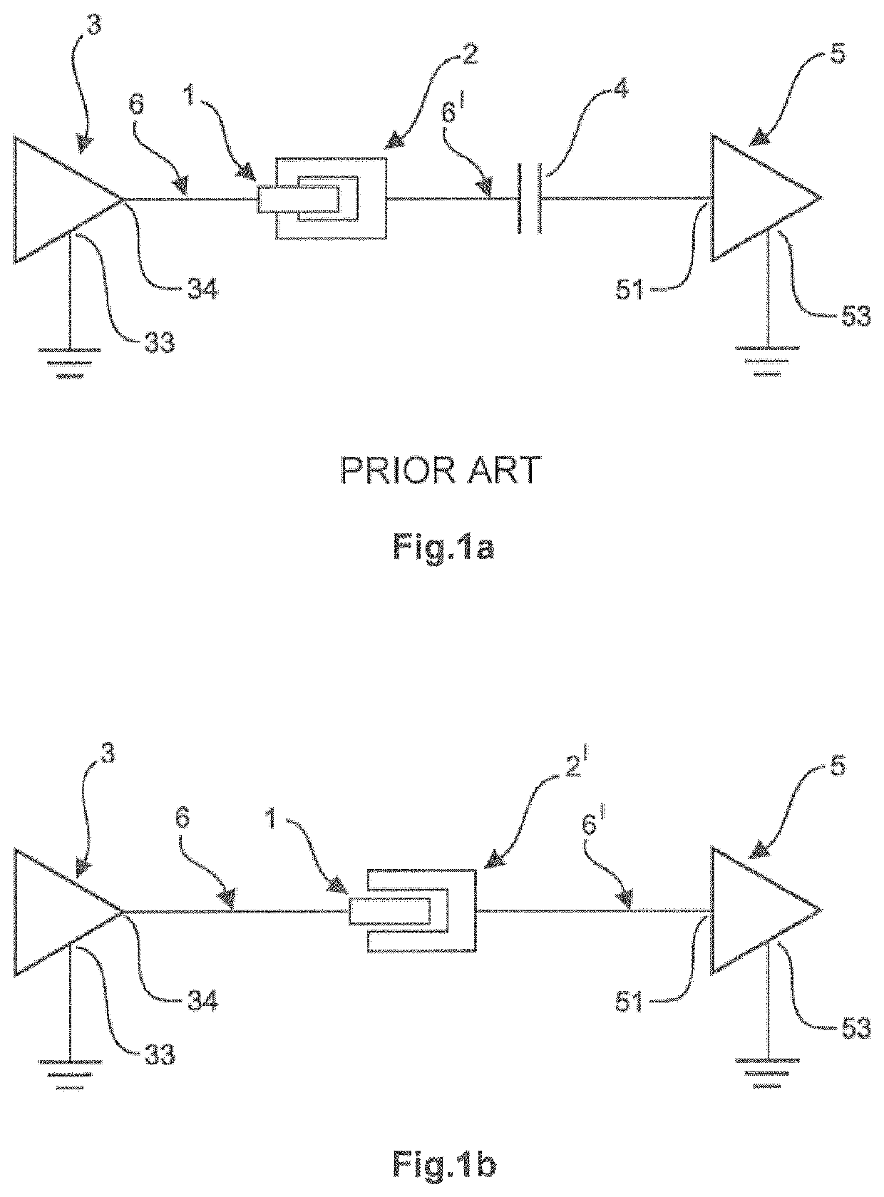
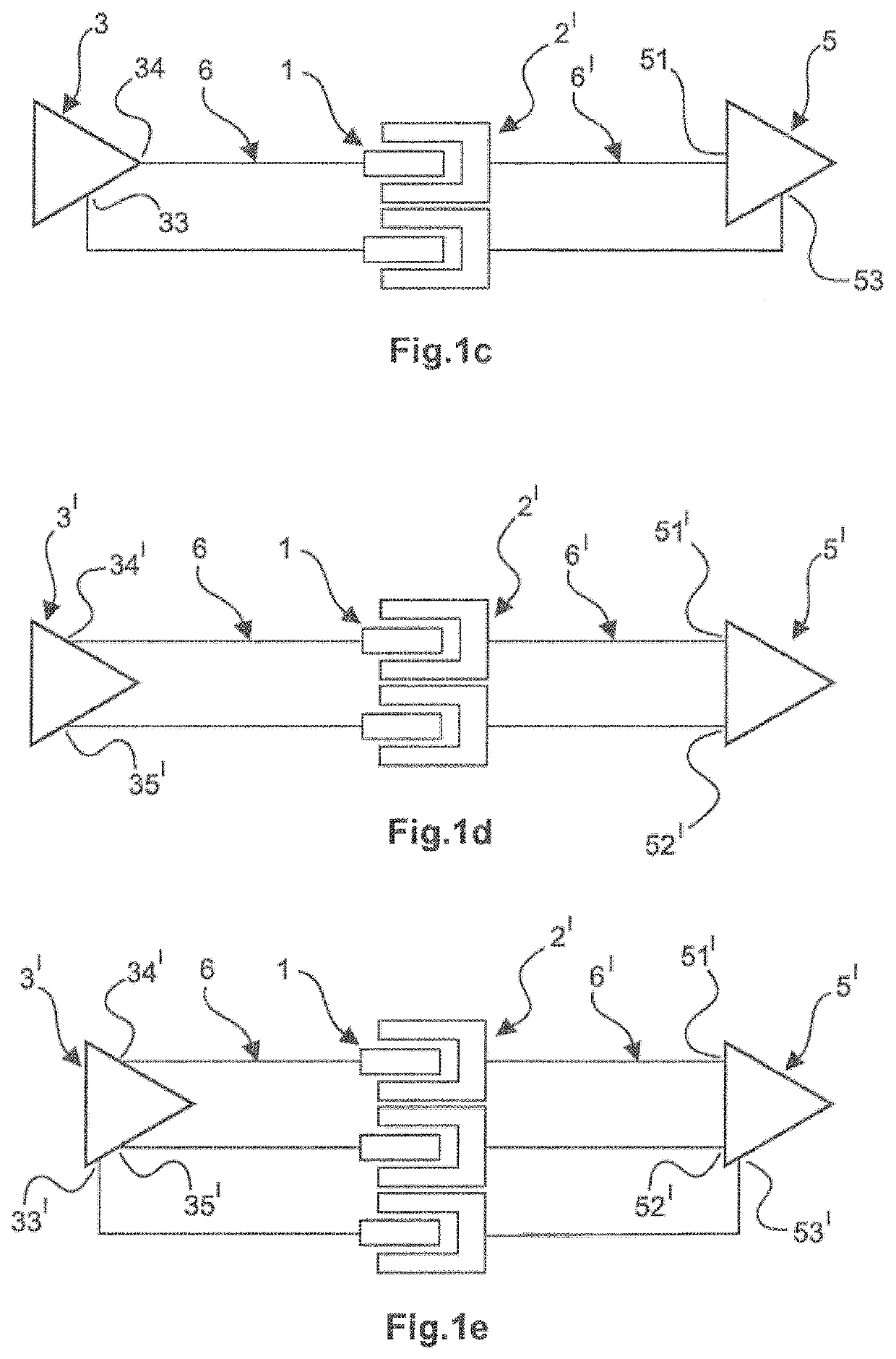
[0056]FIG. 1 shows a circuit diagram of a conventional plug-in connection, that is to say a plug-in connection which corresponds to the prior art. Here, a primary-side electronics system 3 is firstly connected to an associated reference ground connection by way of a ground connection 33 which is provided for this purpose and is furthermore electrically conductively connected, for example by crimping or soldering, to a cable connection region of a pin contact 1 by way of an output 34 via a primary-side line 6.

[0057]At the plug-in end, this contact 1 is electrically conductively connected to a conventional socket contact 2. The socket contact 2 is connected in a DC-isolated manner to an input 51 of a secondary side electronics system 5, which is further connected to an associated reference ground connection by way of a ground connection 53 which is provided for this purpose, by way of its cable connection region via a secondary-side line 6′ and via a coupling capacitor 4.

[0058]FIG. 1b...


PUM


Abstract

Provided is a plug connection which ensures signal integrity, in particular at high data rates and with a large number of plug-in cycles, in a cost-effective manner. A dielectric is in each case arranged between the pin contacts of a connector and the socket contacts of a mating connector to ensure galvanic isolation and capacitive connection between them. In this way the connected circuit electronics can be simplified. There is no need for a coupling capacitor and impedance matching can be performed the geometric arrangement of the contacts. In particular, it ensures that there is a variety of different plug connections to choose from with different properties, in particular with different impedances and capacitances.

Description

BACKGROUND OF THE INVENTION[0001]The invention is based on a plug-in connection comprising a plug and a mating plug, wherein the plug has a plurality of electrically conductive pin contacts and the mating plug has a plurality of associated electrically conductive socket contacts.[0002]Plug-in connections of this kind are required, for example, in the rail sector in order to transmit signals, in particular radio frequency digital signals, within so-called train couplings between individual carriages.DESCRIPTION OF THE PRIOR ART[0003]At high data rates, for example in the frequency range of 1 GHz and more, plug-in connectors are often used, in particular, within train couplings, said plug-in connectors accordingly transmitting radio-frequency digital signals, for example, between the individual carriages of a train.[0004]A fundamental problem is that conventional plug-in connector contacts which are suitable for transmitting high data rates of this kind, that is to say of, for example...

Claims


Application Information

Patent Timeline
Patent Type & Authority Patents(United States)
IPC IPC(8): H01R13/6471H01R13/04H04B5/00B61G5/10H01R13/10
CPCH01R13/10H01R13/6471H04B5/0012B61G5/10H01R13/04H04B5/22
Inventor HAVERMANN, GERT
Owner HARTING ELECTRIC GMBH & CO KG
Learn More