
Control method and associated control system

A control method and control signal technology, which is applied in the field of rotating motor control, controlling permanent magnet synchronous motor and synchronous reluctance motor, and can solve stability problems and other problems

Pending Publication Date: 2021-07-23
INST FR DU PETROLE
View PDF5 Cites 0 Cited by
  • Summary
  • Abstract
  • Description
  • Claims
  • Application Information

AI Technical Summary

Problems solved by technology

This is due to the fact that if the voltage applied to the motor is maximum, only the phase of said voltage will be the degree of freedom to control the rotating motor, which will cause stability problems

Method used


Image

  • Control method and associated control system
  • Control method and associated control system
  • Control method and associated control system

Examples


Embodiment Construction

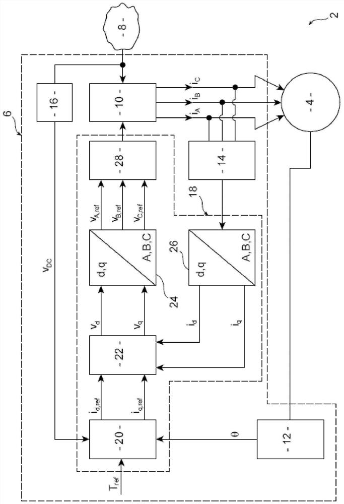
[0053] figure 1 The device 2 is shown comprising an associated electric rotating machine 4 and a control system 6 according to the invention for controlling the electric rotating machine. The device 2 also includes an electrical energy source 8, such as a direct voltage bus.

[0054] The rotating electrical machine 4 is a permanent magnet synchronous or synchronous reluctance three-phase rotating electrical machine, specifically a permanent magnet assisted synchronous reluctance three-phase rotating electrical machine.

[0055] The rotating electrical machine 4 has three inputs identified by the letters A, B, C respectively. Each input A, B, C corresponds to a phase of the stator of the rotating electrical machine 4 .

[0056] Quantities relating to a given input to the rotating electrical machine 4 will therefore have a subscript letter associated with said input.

[0057] The control system 6 is intended to control the power supplied to the rotating electrical machine 4 o...


PUM


Abstract

The invention relates to a method for controlling a three phase synchronous-reluctance or synchronous rotating machine (4) with permanent magnets, comprising the following steps: - measuring a current (iA, iB, iC) flowing in each of the phases of a stator of the rotating machine (4); - first calculation, by means of a single proportional-integral controller, of a commutation control signal for controlling an inverter (10), as a function of each measured current (iA, iB, iC), and a target value (Tref) of a mechanical torque supplied by the rotating machine (4) or of a target value of an angular velocity of a rotor of the rotating machine (4) with respect to the stator, the inverter (10) being configured to convey electrical power between a DC source (8) of electrical power and each phase of the stator of the rotating machine (4); - control of the inverter (10) by means of a calculated commutation control signal.

Description

technical field [0001] The invention relates to a method of controlling a permanent magnet synchronous or synchronous reluctance three-phase rotating electrical machine. The invention also relates to the control system. The invention relates to the field of control of rotating electrical machines, in particular to the field of controlling permanent magnet synchronous motors and synchronous reluctance motors. Background technique [0002] It is known to use rotating electric machines such as permanent magnet synchronous machines or synchronous reluctance machines, in particular permanent magnet assisted synchronous reluctance machines. Such rotating electrical machines are used eg in the field of propulsion to generate engine torque eg on vehicles such as motor vehicles. [0003] Document FR-3,051,296 A1 describes, for example, a permanent magnet assisted synchronous reluctance machine. [0004] Such rotating electrical machines are advantageous because when the so-called ...

Claims


Application Information

Patent Timeline
Patent Type & Authority Applications(China)
IPC IPC(8): H02P23/00H02P6/10
CPCH02P6/10H02P23/0027H02P23/009H02P21/22H02P27/12H02P2207/05
Inventor E·库恩茨曼F·维达尔-纳凯W·迪布
Owner INST FR DU PETROLE
Features
  • Generate Ideas
  • Intellectual Property
  • Life Sciences
  • Materials
  • Tech Scout
  • Unparalleled Data Quality
  • Higher Quality Content
  • 60% Fewer Hallucinations
Learn More