A kind of foundation pit deformation monitoring device

A technology for deformation monitoring and foundation pits, which is applied in the direction of measuring devices, electrical devices, and infrastructure engineering, etc. It can solve the problems of difficult comprehensive and accurate real-time monitoring, continuous monitoring of cracks in foundation pit support structures, and high work intensity. And other issues

Active Publication Date: 2022-07-01
FOSHAN XINYI CONSTR GROUP
View PDF4 Cites 0 Cited by
  • Summary
  • Abstract
  • Description
  • Claims
  • Application Information

AI Technical Summary

Problems solved by technology

[0003] The above methods are not easy to realize the continuous monitoring of cracks in the foundation pit support structure, and all of them require monitoring personnel to go to the site for regular or irregular monitoring. Only representative cracks are monitored, which has certain limitations and is not easy to carry out comprehensive and accurate monitoring. The real-time monitoring and high work intensity, especially during the excavation and use process, due to overloading, over-excavation, water penetration, landslides, uplifts, overturning, etc., cause local cracks to quickly dislocate and develop cracks in the support of the foundation pit, the above mentioned The current monitoring method fails to inform the workers around the collapsed surface to evacuate the dangerous area in a very short time (within a few seconds)

Method used


Image

  • A kind of foundation pit deformation monitoring device
  • A kind of foundation pit deformation monitoring device
  • A kind of foundation pit deformation monitoring device

Examples


Embodiment 1

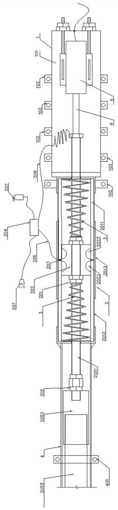
[0015] Example 1: as figure 1 As shown, the present invention includes a fixed end 1 and a monitoring member 2 disposed on the fixed end 1. The fixed end 1 includes a fixed end bracket 101 and a fixed terminal 102 disposed around the fixed end bracket 101. The monitoring member 2 includes a threaded connection or The cylindrical object 201 fixed on the fixed end bracket 101 of the fixed end 1 by welding, the cylindrical conductive slider 202 slidably disposed in the cylindrical object 201, the conductive ring 203 disposed in the middle of the inner cavity of the cylindrical object 201, the detection The control device 204, the end of the conductive slider 202 away from the fixed end 1 is connected with a detection rod 205, the conductive ring 203 and the conductive slider 202 are respectively connected with the detection control device 204 through the wire 206, and the detection control device 204 controls the alarm (sound). light alarm) 207 works.

[0016] Preferably, the ba...

Embodiment 2

[0021] Example 2: as figure 2 As shown, this embodiment is based on Embodiment 1, the middle of the conductive slider 202 is a detection segment, and grooves 2022 are provided on the conductive slider 202 on both sides of the detection segment. Using the groove 2022, when the required detection section is short, the groove 2022 can realize the monitoring of the maximum deformation of the monitored object in the foundation pit, and at the same time, it does not affect the conductive slider 202 outside the groove 2022. Guided by other parts, it smoothly slides in a straight line in the cylindrical object 201 .

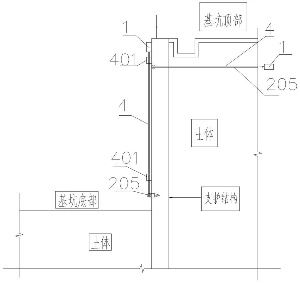
[0022] like image 3 , 4 As shown in the figure, when in use, fix the fixed end 1 at the place where the deformation of the foundation pit support is relatively small (inner corner, support node, etc.) layer, soft soil layer, etc.). At the beginning, since the conductive slider 202 is located in the conductive ring 203, the conductive slider 202 and the conductive r...


PUM


Abstract

A foundation pit deformation monitoring device is characterized in that it comprises a fixed end and a monitoring member arranged at the fixed end, and the monitoring member comprises a cylindrical object fixed on the fixed end, a conductive slider slidably arranged in the cylindrical object, and a monitoring member arranged in the cylindrical object. The conductive ring and the detection control device in the middle of the inner cavity are connected with a detection rod at the end of the conductive slider away from the fixed end, and the conductive ring and the conductive slider are connected with the detection control device through wires. Compared with the prior art, the present invention has the advantages of being able to continuously perform overall detection in real time, and to issue a warning of dangerous sections in time before a collapse accident is about to occur.

Description

technical field [0001] The invention relates to a deformation monitoring technology, in particular to a deformation monitoring technology of a building foundation pit. Background technique [0002] With the rapid development of the domestic economy, foundation pit supports for large-scale and high-rise structures continue to emerge. Affected by uncertain factors, serious accidents such as the collapse of foundation pit support structures occur from time to time, causing serious damage to the life and property of the country and the people. loss. For this reason, people use some monitoring and alarm methods to issue warnings before the collapse accident is about to occur. For the detection methods of cracks in the foundation pit supporting structure, tools such as scales, vernier calipers, coordinate grid plates, crack meters and crack meters are mainly used. In the process of testing, it is necessary to conduct crack investigation on buildings (structures) and roads within ...

Claims


Application Information

Patent Timeline
Patent Type & Authority Patents(China)
IPC IPC(8): G01B7/00E02D33/00
CPCE02D33/00
Inventor 简洛文冼学威吴浩辉周全柯苹麦启明杨华才潘梅胤
Owner FOSHAN XINYI CONSTR GROUP
Why Eureka
Try Eureka