Multifunctional tunnel supporting pointed machine

A multifunctional and tunnel technology, applied in maintenance and safety accessories, metal processing machinery parts, metal processing, etc., can solve problems such as poor circulation, reduced service life of devices, and poor heat dissipation effect of processing tanks, so as to speed up heat dissipation and improve The effect of improving the service life and improving the overall operating time

Pending Publication Date: 2022-01-14
CHINA RAILWAY CONSTR BRIDGE ENG BUREAU GRP OF THE FIFTH ENG +1
View PDF12 Cites 0 Cited by
  • Summary
  • Abstract
  • Description
  • Claims
  • Application Information

AI Technical Summary

Problems solved by technology

[0003] The Chinese patent with the publication number CN111347103B discloses a tunnel grouting small catheter tip machine, the catheter is heated and enters the processing tank, and the tool is driven by the pulley to process the front part of the catheter, and the tool directly contacts the heated catheter , after the gas enters through the air inlet, it passes through the air inlet pipe IV, the air inlet pipe III, the air inlet pipe II, the air inlet pipe I, the air guide pipe, and the air inlet hole, and then enters into the spiral air passage, and the gas produced by the tool under the action of friction The heat is taken away, and then the gas leaves the equipment from the other end of the spiral air channel. During the movement of the gas in the spiral air channel, a negative pressure will be formed at one end of the negative pressure tube to absorb the debris generated by cutting in the processing tank. , the particles at the suction point leave the equipment with the airflow in the spiral air channel; but too many particles will block the spiral air channel, making the air flow and circulation not smooth, resulting in poor heat dissipation effect of the processing tank and reducing the service life of the device

Method used


Image

  • Multifunctional tunnel supporting pointed machine
  • Multifunctional tunnel supporting pointed machine
  • Multifunctional tunnel supporting pointed machine

Examples


Embodiment 1

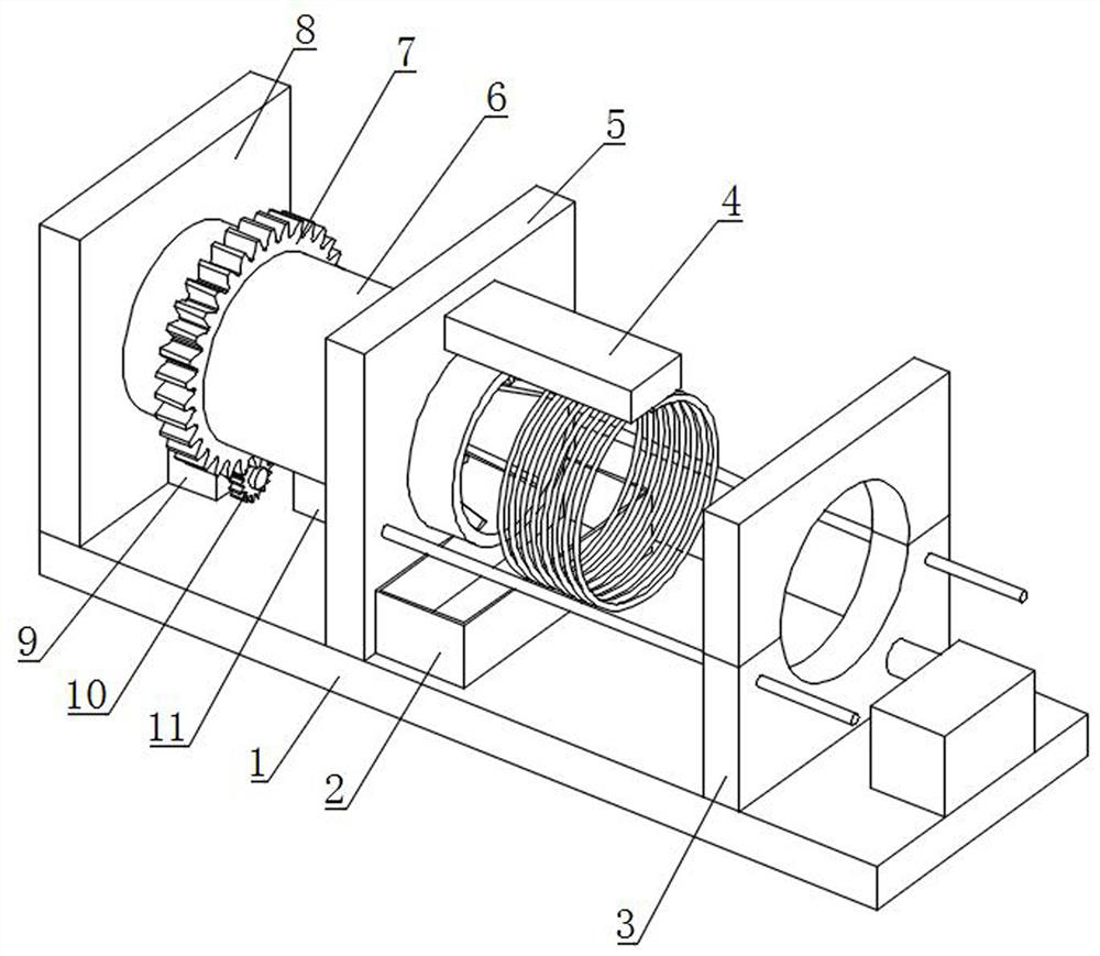
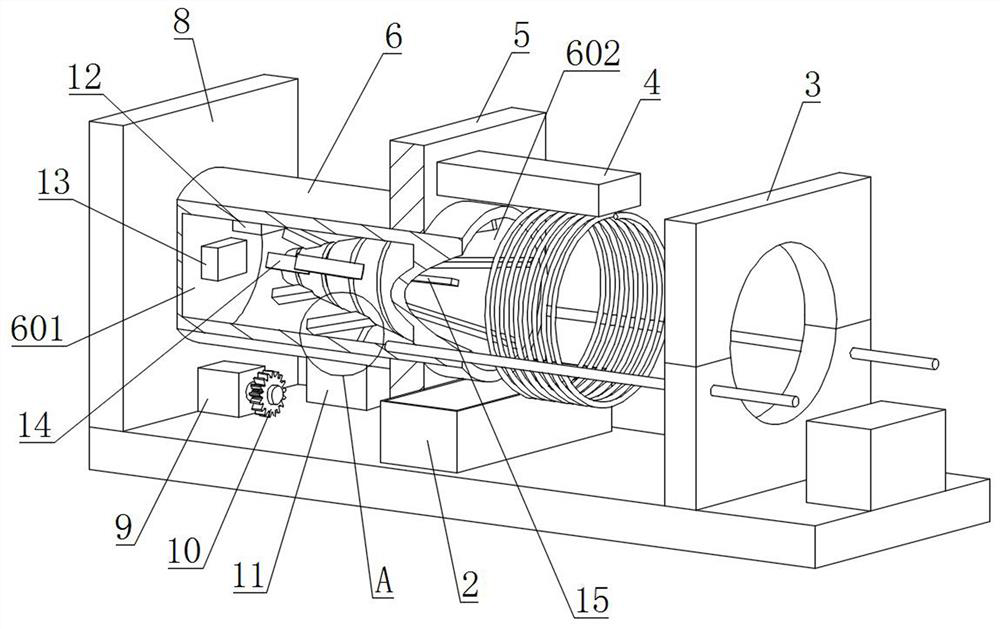
[0028] The main structure of this embodiment, such as Figure 1~3 As shown, it includes a bottom plate 1, a collection box 2, a first support plate 5, a cylinder 6, a second support plate 8, a motor 9, a temperature detector 12, a refrigerator 13, a plurality of cooling fins 14 and a plurality of blades 15; The first support plate 5 and the second support plate 8 are installed side by side on the base plate 1, the first support plate 5 is provided with a heating assembly 4 for heating the workpiece; The mobile component of 3;

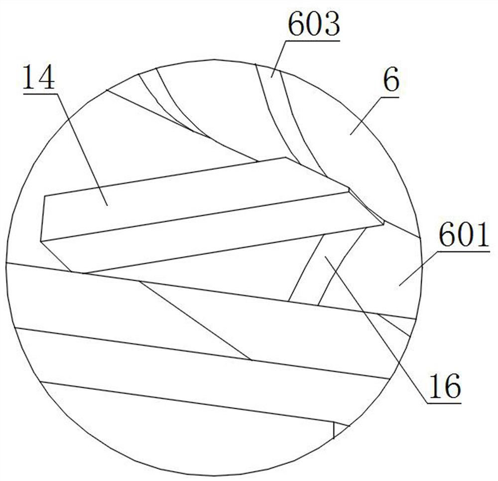
[0029] One end of the cylinder 6 is rotatably connected to the second support plate 8, the other end of the cylinder 6 passes through the first support plate 5, and the end of the cylinder 6 passing through the first support plate 5 is provided with a processing groove 602; The projection shape is conical; the cylinder 6 is provided with an installation warehouse 601; the inner wall of the installation warehouse 601 is provided with a cooling groove 60...

Embodiment 2

[0033] In this embodiment, on the basis of the foregoing embodiments, a vacuum cleaner 11 and a connecting pipe 16 are further added, such as Figure 1~3 As shown; the vacuum cleaner 11 is installed on the cylinder 6; one end of the connecting pipe 16 is connected to the air inlet port of the vacuum cleaner 11, and the other end of the connecting pipe 16 extends into the processing tank 602. Start the vacuum cleaner 11 during use, and the remaining processing debris in the processing tank 602 is sucked in the vacuum cleaner 11 through the connecting pipe 16, and the inside of the processing tank 602 is cleaned to prevent the debris from adhering to a plurality of blades 15. Multiple blades 15 are protected. Other parts of this embodiment are the same as those of the foregoing embodiment, and will not be repeated here.

Embodiment 3

[0035] On the basis of the foregoing embodiments, this embodiment further includes a driving gear 10 and a driven gear 7; the driving gear 10 is mounted on the output shaft of the motor 9; the driven gear 7 is mounted on the cylinder 6, The driven gear 7 is engaged with the driving gear 10 . The driven gear 7 is meshed with the driving gear 10 so that the transmission of the motor 9 is more stable. Other parts of this embodiment are the same as those of the foregoing embodiment, and will not be repeated here.


PUM


Abstract

The invention discloses a multifunctional tunnel supporting pointed machine which comprises a bottom plate, a collecting box, a cylinder, a motor, a temperature detector, a refrigerator, a plurality of cooling fins and a plurality of blades. A first supporting plate and a second supporting plate are arranged on the bottom plate, and a moving assembly is arranged on the bottom plate; a heating assembly is arranged on the first supporting plate; the cylinder is connected with the second supporting plate and provided with a machining groove; a mounting bin is arranged in the cylinder; a heat dissipation groove is formed in the inner wall of the mounting bin; the plurality of radiating fins are mounted in the mounting bin; the plurality of blades are connected with the inner wall of a processing bin; a controller is arranged on the second supporting plate; the temperature detector and the refrigerator are both mounted in the mounting bin, and the temperature detector, the refrigerator, the heating assembly and the moving assembly are electrically connected with the controller; the motor is in transmission connection with the cylinder; and a collecting box is mounted on the bottom plate. By means of the multifunctional tunnel supporting pointed machine, heat dissipation and scrap collection can be conveniently carried out on the device, and the practicability of the device is improved.

Description

technical field [0001] The invention relates to the technical field of tunnel construction equipment, in particular to a multifunctional tunnel support tip machine. Background technique [0002] The tip machine is a kind of automatic processing for the tapered tip of the advanced small catheter. It has the characteristics of low noise, easy operation, high output and stable performance. The forming time of the workpiece is short, the efficiency is high, the processing surface is smooth, and the workpiece has no scars. The front part of the catheter is heated by the energized coil to make it red hot and soft, and then the front part is processed by the tool. The whole processing process does not require manual intervention. Can be fully automated. [0003] The Chinese patent with the publication number CN111347103B discloses a tunnel grouting small catheter tip machine, the catheter is heated and enters the processing tank, and the tool is driven by the pulley to process the...

Claims


Application Information

Patent Timeline
Patent Type & Authority Applications(China)
IPC IPC(8): B23D79/00B23P25/00B23Q11/10
CPCB23D79/00B23Q11/10B23P25/00
Inventor 何十美张玉伟郭建强苏春生郑彬刘海波王松涛
Owner CHINA RAILWAY CONSTR BRIDGE ENG BUREAU GRP OF THE FIFTH ENG
Why Eureka
Try Eureka