Foundation pit deformation monitoring device

A deformation monitoring and foundation pit technology, which is applied in foundation structure engineering, foundation structure testing, construction, etc., can solve the problem of continuous monitoring of cracks in foundation pit support structures, high work intensity, and difficult comprehensive and accurate real-time monitoring And other issues

Active Publication Date: 2021-07-27
FOSHAN XINYI CONSTR GROUP
View PDF4 Cites 0 Cited by
  • Summary
  • Abstract
  • Description
  • Claims
  • Application Information

AI Technical Summary

Problems solved by technology

[0003] The above methods are not easy to realize the continuous monitoring of cracks in the foundation pit support structure, and all of them require monitoring personnel to go to the site for regular or irregular monitoring. Only representative cracks are monitored, which has certain limitations and is not easy to carry out comprehensive and accurate monitoring. The real-time monitoring and high work intensity, especially during the excavation and use process, due to overloading, over-excavation, water penetration, landslides, uplifts, overturning, etc., cause local cracks to quickly dislocate and develop cracks in the support of the foundation pit, the above mentioned The current monitoring method fails to inform the workers around the collapsed surface to evacuate the dangerous area in a very short time (within a few seconds)

Method used


Image

  • Foundation pit deformation monitoring device
  • Foundation pit deformation monitoring device
  • Foundation pit deformation monitoring device

Examples


Embodiment 1

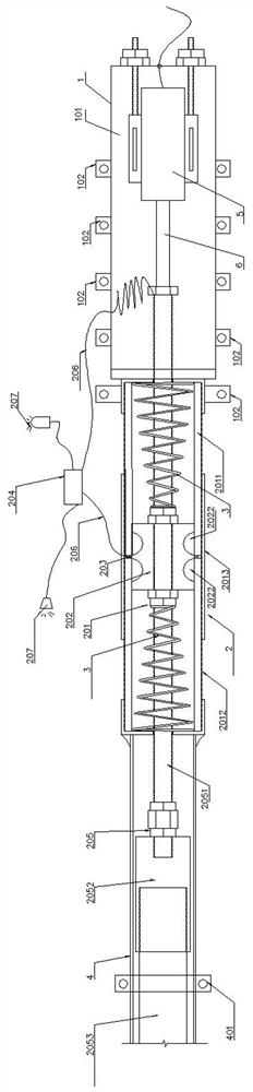
[0015] Embodiment 1: as figure 1 As shown, the present invention includes a fixed end 1, a monitoring member 2 arranged on the fixed end 1, the fixed end 1 includes a fixed end bracket 101, a fixed terminal 102 arranged on the periphery of the fixed end bracket 101, and the monitoring structure 2 includes a screw thread or The cylindrical object 201 fixed on the fixed end bracket 101 of the fixed end 1 by welding, the columnar conductive slider 202 slidably arranged in the cylindrical object 201, the conductive ring 203 arranged in the middle of the inner cavity of the cylindrical object 201, and the detection The control device 204, the end of the conductive slider 202 away from the fixed end 1 is connected with a detection rod 205, the conductive ring 203 and the conductive slider 202 are connected to the detection control device 204 through a wire 206, and the detection control device 204 controls the alarm (acousto-optic alarm) 207 work.

[0016] Preferably, the barrel 20...

Embodiment 2

[0021] Embodiment 2: as figure 2 As shown, this embodiment is based on Embodiment 1. The middle part of the conductive slider 202 is a detection section 2021 , and the conductive slider 202 on both sides of the detection section 2021 is provided with grooves 2022 . Using the groove 2022, when the required detection section 2021 is short, the monitoring of the maximum deformation of the object to be monitored in the foundation pit can be realized through the groove 2022, and at the same time, it does not affect the conductive slider 202 outside the groove 2022 Guided by other parts of the cylinder, it slides smoothly in a straight line in the barrel 201.

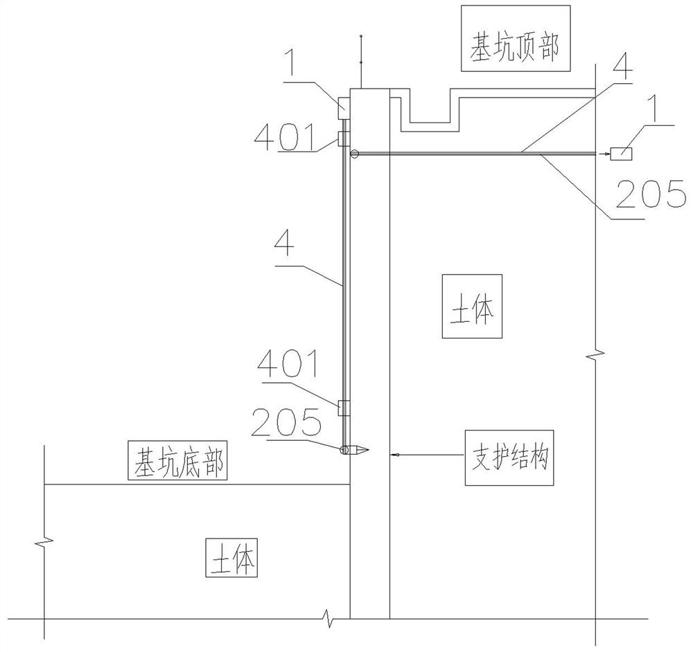
[0022] Such as image 3 , 4 As shown, when in use, the fixed end 1 is fixed at the place where the support of foundation pit A is relatively small in deformation (inner corner, support node, etc.), and the far end of the detection rod 205 is fixed at a certain distance (the outer corner of the foundation pit, across differ...


PUM


Abstract

The invention relates to a foundation pit deformation monitoring device. The device is characterized by comprising a fixed end and a monitoring component arranged at the fixed end, wherein the monitoring component comprises a barrel-shaped object fixed at the fixed end, a conductive sliding block arranged in the barrel-shaped object in a sliding mode, a conductive ring arranged in the middle of an inner cavity of the barrel-shaped object and a detection control device, the end, away from the fixed end, of the conductive sliding block is connected with a detection rod, and the conductive ring and the conductive sliding block are connected with the detection control device through wires. Compared with the prior art, the foundation pit deformation monitoring device has the advantages that full detection can be continuously carried out in real time, and a dangerous section alarm can be timely sent out before a collapse accident occurs.

Description

technical field [0001] The invention relates to a deformation monitoring technology, in particular to a deformation monitoring technology of building foundation pits. Background technique [0002] With the rapid development of the domestic economy, foundation pit support for large-scale and high-rise structure construction continues to emerge. Affected by uncertain factors, serious accidents of foundation pit support structure collapse will occur from time to time, causing serious damage to the life and property of the country and the people. loss. For this reason, people use some monitoring and alarming methods to warn before the collapse accident occurs. For the crack detection of foundation pit support structure, tools such as scale, vernier caliper, coordinate grid plate, crack meter and crack meter are mainly used. To carry out detection, the process needs to conduct crack investigation on buildings (structures) and roads within the scope of its influence before the co...

Claims


Application Information

Patent Timeline
Patent Type & Authority Applications(China)
IPC IPC(8): E02D33/00
CPCE02D33/00
Inventor 简洛文冼学威吴浩辉周全柯苹麦启明杨华才潘梅胤
Owner FOSHAN XINYI CONSTR GROUP
Why Eureka
Try Eureka