
Joint connecting structure and assembly type beam frame

A node connection and connector technology, which is applied in the direction of building structure and construction, and can solve the problem that the welding position affects the strength of the node connection structure.

Active Publication Date: 2021-07-27
CHINA RAILWAY SIXTH GRP CO LTD
View PDF5 Cites 0 Cited by
  • Summary
  • Abstract
  • Description
  • Claims
  • Application Information

AI Technical Summary

Problems solved by technology

[0002] Existing beam frames are usually formed by connecting a plurality of horizontal frames arranged at intervals in the height direction through columns. The joint connection structure of the beam frame is usually formed by directly welding the end faces of the beams to the columns. However, when the beams and columns pass through When welding and fixing together, welding stress is likely to be generated at the welding position and affect the strength of the joint connection structure. Therefore, a joint connection structure and an assembled beam frame with high connection strength are needed

Method used


Image

  • Joint connecting structure and assembly type beam frame
  • Joint connecting structure and assembly type beam frame
  • Joint connecting structure and assembly type beam frame

Examples


Embodiment

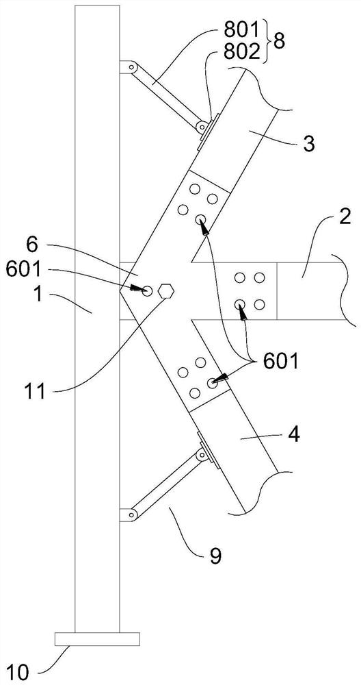
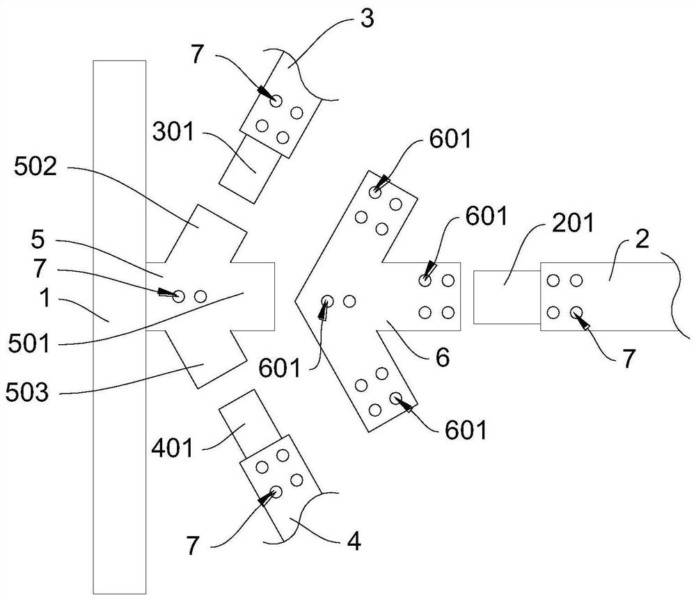
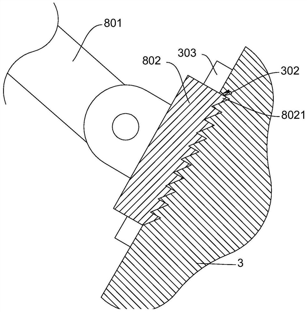
[0039] Please refer to Figure 1 to Figure 6, shows a node connection structure and a prefabricated beam frame provided by an embodiment of the present invention, and the details are as follows.

[0040] Such as figure 1 with figure 2 As shown, the embodiment of the present invention provides a node connection structure, which includes a main beam 1, a cross beam 2, a first inclined support beam 3, a second inclined support beam 4, a connecting head 5 and a connecting piece 6, wherein the main beam 1, The beam 2, the first slanting support beam 3 and the second slanting support beam 4 are all made of rectangular steel. The main beam 1 is arranged vertically to provide vertical support, and the crossbeam 2 is arranged horizontally to provide horizontal support. The first slanting support beam 3 and the second slanting support beam 4 are arranged inclined upwards and downwards respectively to provide support in an oblique direction. The connecting head 5 plays the role of c...


PUM


Abstract

The invention provides a joint connecting structure, and relates to the field of framework structure design. According to the technical scheme, the joint connecting structure comprises a main beam, a cross beam, a first inclined supporting beam, a second inclined supporting beam, a connector and a connecting piece, wherein the connector is fixedly connected with the main beam; the connector comprises a transverse branch head, an upper inclined branch head and a lower inclined branch head, the upper inclined branch head and the lower inclined branch head are symmetrically distributed relative to the transverse branch head, and the transverse branch head, the upper inclined branch head and the lower inclined branch head are respectively connected with the cross beam, the first inclined supporting beam and the second inclined supporting beam; the connecting piece is provided with a plurality of first penetrating holes; the connector, the cross beam, the first inclined supporting beam and the second inclined supporting beam are provided with second penetrating holes; and the second penetrating holes are matched with the first penetrating holes. The joint connecting structure has the beneficial effects of high joint connecting strength and long service life. The invention also provides an assembly type beam frame which comprises a plurality of mutually-assembled joint connecting structures and has the beneficial effects that the joint connecting strength is high, and breaking cannot easily occur.

Description

technical field [0001] The invention relates to the field of frame structure design, in particular to a node connection structure and an assembled beam frame. Background technique [0002] Existing beam frames are usually formed by connecting multiple horizontal frames arranged at intervals in the height direction through columns, and the joint connection structure of the beam frame is usually formed by directly welding the end faces of the beams to the columns. However, when the beams and columns pass through When welding and fixing together, welding stress is likely to be generated at the welding position and affect the strength of the node connection structure. Therefore, a node connection structure and an assembled beam frame with high connection strength are required. Contents of the invention [0003] The purpose of the present invention is to provide a node connection structure, which can provide corresponding solutions to the problems existing in the prior art, and...

Claims


Application Information

Patent Timeline
Patent Type & Authority Applications(China)
IPC IPC(8): E04B1/24E04B1/58
CPCE04B1/24E04B1/2403E04B1/58E04B2001/2406E04B2001/2415E04B2001/2418E04B2001/2457
Inventor 韩毅褚文刘玲鹿青安瑞刚王世奇段晓东
Owner CHINA RAILWAY SIXTH GRP CO LTD
Learn More