Display frame mounting machine with corner perpendicularity detection function

A verticality and display technology, which is applied in the field of display frame framing machine with corner verticality detection function, can solve the problems of insufficient tightness of display assembly and inconvenient use for users, and achieves easy reception and collection, convenient placement of items, and easy assembly convenient effect

Pending Publication Date: 2021-07-27
长沙市焕峰自动化设备有限公司
0 Cites 0 Cited by

AI-Extracted Technical Summary

Problems solved by technology

[0004] The object of the present invention is to provide a display frame framing machine with a corner perpendicularity detection function to solve the inconvenience of measuring the verticality of the frame during the use of the existing display frame framing machine proposed in the backgroun...

Method used

Placement frame 8 is installed on the left end of limiter 14 outside, and the inside of placement frame 8 is provided with adjusting device 11, and adjusting device 11 comprises the first hydraulic gas rod 1101 and positioning plate 1102, and the inside setting of adjusting device 11 There is a first hydraulic gas rod 1101, and a positioning plate 1102 is installed on the outer end of the first hydraulic gas rod 1101, and the positioning plate 1102 and the first hydraulic gas rod 1101 are tightly fitted, and the outside of the first hydraulic gas rod 1101 One end is connected to the adjustment device 11 by welding, and the frame placed inside the frame 8 can be moved by using the action of the first hydraulic gas rod 1101 to drive the positioning plate 1102 to move the position of the frame. The limit is fixed to avoid the problem of assembly failure caused by position deviation when framing the article. At the same time, when the adjustment device 11 is used to limit the frame, the function of the infrared transmitter 15 can be used to detect t...

Abstract

The invention relates to a display frame framing machine with a corner perpendicularity detection function, which comprises a machining part and an infrared emitter, a containing frame is arranged at the bottom of the machining part, a supporting device is installed at one end of the exterior of the containing frame, and a main body is arranged at one end of the exterior of the supporting device; the display frame framing machine with the corner perpendicularity detection function has the beneficial effects that through the arrangement of the collecting device, machined parts can be collected through the design of the collecting device after framing of the machined parts is completed; when an inclined plate in the collecting device is stressed, the inclined plate can synchronously cooperate with the interaction between a limiting groove and a connecting shaft to rotate, the situation that a machined part is directly and flatly placed on the outer surface of a containing bottom plate due to the gravity effect is avoided, gravity damage to the machined part is reduced, and when the inclined plate inclines, the inclined plate can be supported through the effect of a connecting spring; and through the design of a connecting spring, buffering can be conducted when the inclined plate is stressed, and the machined parts can be conveniently received and collected.

Application Domain

Active open surveying meansUsing optical means +1

Technology Topic

Infrared emitterEngineering +4

Image

  • Display frame mounting machine with corner perpendicularity detection function
  • Display frame mounting machine with corner perpendicularity detection function
  • Display frame mounting machine with corner perpendicularity detection function

Examples

  • Experimental program(1)

Example Embodiment

[0027] Next, the technical solutions in the embodiments of the present invention will be apparent from the embodiment of the present invention, and it is clearly described, and it is understood that the described embodiments are merely embodiments of the present invention, not all of the embodiments.
[0028] In the description of the present invention, unless otherwise stated, the meaning of "multiple" is two or more; the term "upper", "lower", "left", "right", "within", "outside" , "Front end", "backend", "head", "tail", etc. The direction or position of the indication is based on the orientation or positional relationship shown in the drawings, is only for ease of describing the invention and simplified description, not Indicates or suggests that the device or element refers to have a specific orientation, constructed and operated in a specific orientation, and thus is not to be construed as limiting the invention, in addition, the term "first", "second", "third", etc. For description purposes only, it cannot be understood as instructions or implies relative importance.
[0029] In the description of the present invention, it is to be noted that the term "connected", "connection",, unless otherwise express, "Connect", should be a generalized understanding, for example, may be a fixed connection, or a detachable connection, or integral Connection; it can be mechanical connection, or an electrical connection; it can be directly connected, or indirectly connected by an intermediate medium, and for those skilled in the art, it can be understood that the above terms in the present invention .
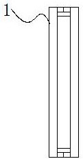
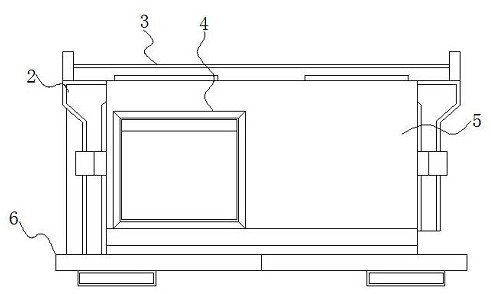
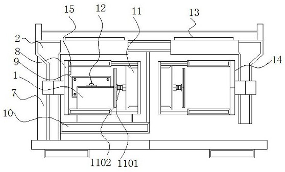
[0030] See Figure 1-6The present invention provides a technical solution: a display frame for the edge vertical degree detection function, including the processing member 1, the main body 2, the electric rail 3, the collecting device 4, the inner frame 401, and placed the bottom plate 402. The limit slot 403, the connecting shaft 404, the connection spring 405, the sloping plate 406, the baffle 5, the base 6, the support device 7, the transfer block 701, the first electric push rod 702, the placing frame 8, the fixed plate 9, placement The frame 10, the adjustment device 11, the first hydraulic air rod 1101, the positioning plate 1102, the second electric push rod 12, the connection block 13, the limit device 14, push plate 1401, connection frame 1402, the second hydraulic gas rod 1403 and infrared rays The transmitter 15, the bottom portion of the processing member 1 is provided with a placing frame 10, and one end of the outer portion of the plastic frame 10 is attached, the support device 7 includes a forward block 701 and a first electric push rod 702, and the inside of the support device 7 is provided. The first electric push rod 702 is provided, and the bottom portion of the first electric push rod 702 is attached, and one end of the outer portion of the shifting block 701 is welded to the placement frame 10, and the bottom and first electric shift block 701 The push rod 702 is a fixed connection, which can be placed in the internal portion of the plastic frame 10 in advance during use, and then the internal transfer block 701 and the first electric push rod 702 can be utilized. The actuating placement rack 10 is adjusted for the upper and lower height, facilitating the processing member 1 inside the placing frame 10 is between the adjustment means 11 and the limit device 14, which is convenient for the frame, and can be placed on the processing member 1 Placement 10 is highly adjusted to provide convenience for item placement.
[0031] One end of the outer portion of the support device 7 is provided with a main body 2, and the exterior of the front end of the main body 2 is mounted having a baffle 5, and a collecting device 4 is provided inside the baffle 5, and a base 6 is mounted outside the bottom of the collecting device 4, collecting device 4. Including the inner frame 401, the bottom plate 402, the limit slot 403, the connecting shaft 404, the connection spring 405, and the sloping plate 406, and the internal frame 401 is provided in the inside of the collecting device 4, and the inner frame 402 is attached, and the bottom plate 402 is attached. The inner portion of the platen 402 is provided with a sloping plate 406, and the top of the sloping plate 406 is connected to the connection spring 405, the interior of the bottom portion of the slant plate 406 is provided, and the interior of the restricted groove 403 is provided with a connecting shaft 404, the connecting shaft 404. There is an active connection between the limit slot 403, and the outer portion of the limit slot 403 is integrated with the sloping plate 406, and the top portion of the slant plate 406 is bonded to the connection spring 405, and can be completed on the processing member 1 Thereafter, the design of the collecting device 4 can be used to collect the processing member 1, and the interaction between the synchronous mating groove 403 and the connecting shaft 404 can be rotated when the slant plate 406 in the collecting device 4 can be rotated, and the processing can be rotated. Part 1 Due to the gravity action of the outer surface of the platen 402, the gravity damage to the processing member 1 is reduced, and the slanting spring 405 can be supported by the action of the connection spring 405 when the slant plate 406 is inclined, and the connection spring 405 can be utilized. The design is buffered when the slant plate 406 is functioning, which is convenient for receiving the processing member 1.
[0032] The top of the main body 2 is provided with an electric slide rail 3, and the right end of the external electric rail 3 is attached, and the electric rail 3 and the main body 2 are not in the same horizontal plane, and the connecting block 13 constitutes a slide by the electric rail 3 and the main body 2. The structure can be placed by manually operating the bodes of the frame to be placed inside the adjustment device 11 and the limit device 14, and then the active device 14 outside the electric rail 3 can be automatically performed using the action of the electric rail 3. The movement of the position allows the border required to make the frame to be aligned, providing convenient, and junction structure for the subsequent assembly of the border, facilitating the user's use.
[0033] The external device 14, the limit device 14 including the push plate 1401, the connection frame 1402, and the second hydraulic barrier 1403, and the inside of the limit device 14 is provided outside the push plate 1401. One end is mounted with the second hydraulic air rod 1403, and one end of the outer portion of the second hydraulic rod 1403 is provided with a connection frame 1402, and the connection frame 1402 and the second hydraulic air rod 1403 are fixed, and the external hydraulic rod 1403 is The push plate 1401 is a bonding connection, and can perform positional adjustment of the push plate 1401 by the action of the second hydraulic barrier 1403, so that the border can be limited, and then the action of the electric rail 3 can be driven to the limit device 14. The movement of the position can be pushed by the position adjustment of the position adjustment, and the border of the second electric push rod 12 is used to push the border after the limit, so that the two sets of borders can be engaged with the display, and after the frame is completed, the frame is completed. The processing member 1 can be advanced to the inside of the collecting device 4 by the push of the second electric push rod 12, so that the processing member 1 is advanced to the inside of the collecting device 4, making it uniform to take it.
[0034] The left end of the limiting device 14 is mounted with place frame 8, and the inside of the placing frame 8 is provided with a adjustment device 11, and the adjustment device 11 includes a first hydraulic gas rod 1101 and a positioning plate 1102, and the internal setting of the adjustment device 11 has a first The hydraulic air rod 1101, one end of the first hydraulic barrier rod 1101 is attached, and between the positioning plate 1102 and the first hydraulic air rod 1101 is closely fitted, and one end and adjustment of the outer portion of the first hydraulic air rod 1101 The device 11 is a solder connection, and can be moved to the position of the position plate 1102 by the first hydraulic barrier 1102 by the first hydraulic barrier 1102, by moving the positioning plate 1102, by moving the position of the positioning plate 1102. Avoid problems that cause the assembly failure when the position is blocked when the item is fed. At the same time, when the edge frame is transmitted to the edge frame, the effect can be perpendicularly detected by the infrared transmitter 15, and the border can be performed. The verticality condition is judged that the outer portion of the rear end of the placing frame 8 is attached, and the second electric push rod 12 is provided inside the fixing plate 9, and the infrared transmitter 15 is located inside the placed frame 8.
[0035] In summary, the display frame of the angular vertical degree detection function can be placed in the adjustment device 11 and the boundary device 14, respectively, and can be placed in the inside of the adjustment device 11 and the limit device 14 when used by manual operation. The border inside the box 8 is placed, and the movement of the positioning plate 1102 can be moved by the active hydraulic rod 1101, and the action of the infrared transmitter 15 can be perpendicular to the action of the infrared transmitter 15 when the border is performed by the first hydraulic barrier 1101. Detective detection, the verticality of the border can be judged, and the border can be fixed to the border by the movement of the positioning plate 1102, and the push plate 1401 can be adjusted to the action of the second hydraulic barrier 1403, thereby It is possible to limit the border, and then synchronized with the action of the electric rail 3 can be moved to the position of the limit device 14, and the processing member 1 of the required assembly is placed inside the placement frame 10 during use during use. Then, the interaction of the support device 7 and the interaction of the first electric push rod 702 can be utilized to perform the upper and lower height adjustment, facilitate the processing member 1 inside the placement 10 in the adjustment device 11 and the limit device 14. Between, it is necessary to provide convenient, the position adjustment is completed, and the interaction of the fixed plate 9 and the second electric push rod 12 can be pushed back to the border after the limit, so that the two sets of borders can be engaged with the display, and the frame is loaded. After the frame end, the processing member 1 can be advanced to the end of the assembly device 4 by the push of the second electric push rod 12, so that the processing member 1 is advanced to the inside of the collecting device 4, and can be synchronized when the slant plate 406 inside the collecting device 4 is synchronized. The interaction between the mixing shaft 403 and the connecting shaft 404 can be rotated, avoiding the processing member 1 directly in the outer surface of the platen 402 due to gravity, reducing the gravity damage to the processing member 1, tilting at the slant plate 406 When the action of the connection spring 405 can be supported by the connection spring 405, the design of the connection spring 405 can be used to be buffered when the slant plate 406 is stressed, and it is convenient for receiving the processing collecting collection, and the interior frame 401 and the collecting device 4 are facilitated. The internal is active connection, and it is possible to take out the interior of the collecting device 4 after the end of the processing member 1 is collected, which is convenient to take the processing member 1 inside the inner frame 401.
[0036] As described above, only the preferred embodiments of the present invention are preferred, but the scope of the invention is not limited thereto, and any techniques, those skilled in the art, according to the present invention, in accordance with the present invention. And its inventive concept is equivalent to alternative or change, which should be covered within the scope of the invention.

PUM

no PUM

Description & Claims & Application Information

We can also present the details of the Description, Claims and Application information to help users get a comprehensive understanding of the technical details of the patent, such as background art, summary of invention, brief description of drawings, description of embodiments, and other original content. On the other hand, users can also determine the specific scope of protection of the technology through the list of claims; as well as understand the changes in the life cycle of the technology with the presentation of the patent timeline. Login to view more.

Similar technology patents

Backlight module and display device

Owner:AU OPTRONICS (SUZHOU) CORP LTD +1

Keyboard with holder

Owner:SHENZHEN DOKING TECH CO LTD

Lens module group assembling system and method of use thereof

InactiveCN101290385AEasy to assemble
Owner:HONG FU JIN PRECISION IND (SHENZHEN) CO LTD +1
Why Eureka
Try Eureka