[0026] The technical solutions in the embodiments of the present invention will be clearly and completely described below with reference to the accompanying drawings in the embodiments of the present invention. Obviously, the described embodiments are only a part of the embodiments of the present invention, not all of the embodiments. The embodiments of the present invention, and all other embodiments obtained by those of ordinary skill in the art without creative work, fall within the protection scope of the present invention.
[0027] In the description of the present invention, unless otherwise stated, "plurality" means two or more; the terms "upper", "lower", "left", "right", "inner", "outer" The orientation or positional relationship indicated by , "front end", "rear end", "head", "tail", etc. are based on the orientation or positional relationship shown in the accompanying drawings, and are only for the convenience of describing the present invention and simplifying the description, not Indicates or implies that the referred device or element must have a specific orientation, be constructed and operate in a specific orientation, and therefore should not be construed as a limitation of the invention, in addition, the terms "first", "second", "third", etc. For descriptive purposes only and should not be construed to indicate or imply relative importance.
[0028]In the description of the present invention, it should be noted that, unless otherwise expressly specified and limited, the terms "connected" and "connected" should be understood in a broad sense, for example, it may be a fixed connection, a detachable connection, or an integral connection. ground connection; it can be a mechanical connection or an electrical connection; it can be directly connected, or indirectly connected through an intermediate medium. .
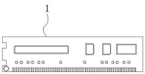
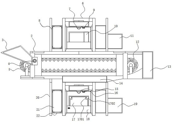
[0029] see Figure 1-5 , the present invention provides a technical solution: a size detection device with data acquisition function for computer graphics card processing, comprising a workpiece 1, a main body 2, an auxiliary feeding frame 3, a connecting shaft 4, a connecting block 5, and a first detection frame. 6. The first detection head 7, the stabilization frame 8, the first camera 9, the fixing device 10, the hydraulic air rod 1001, the micro air rod 1002, the rear plate 1003, the fixed plate 1004, the movable plate 1005, the placing frame 11, the conveyor belt 12 , connecting the receiving frame 13, the guide frame 14, the second detection head 15, the second camera 16, the auxiliary device 17, the rotating shaft 1701, the connecting sleeve 1702, the classification auxiliary device 18, the motor 1801, the transverse cavity 1802, the heat dissipation plate 1803, the classification Plate 1804, placement cavity 1805, water pump 1806, extension pipe 1807, collection frame 19, support frame 20, cover plate 21, side collection frame 22, guide device 23, air pipe 2301, air pump 2302, guide connection device 24, connection block 2401 , connecting frame 2402, electric push rod 2403, push plate 2404 and leakage port 25, a conveyor belt 12 is provided on the outside of the workpiece 1, and an auxiliary feeding frame 3 is installed on the left end outside the conveyor belt 12. The ends are connected with a connecting block 5, and the middle part of the connecting block 5 runs through the connecting shaft 4, the outer end of the connecting shaft 4 is installed with the main body 2, and the upper end outside the main body 2 is provided with a first detection frame 6, the first detection frame 6. A first detection head 7 is installed in the middle of the inside, and a first camera 9 is installed at one end outside the first detection head 7, and a fixing device 10 is installed at the outer end of the bottom of the first camera 9. The fixing device 10 includes a hydraulic gas rod 1001 , a miniature gas rod 1002, a rear plate 1003, a fixed plate 1004 and a movable plate 1005, and a hydraulic gas rod 1001 is arranged in the middle of the fixing device 10, and the bottom of the hydraulic gas rod 1001 is connected with a rear plate 1003, and the rear plate One end outside the 1003 is installed with a fixed plate 1004, one end outside the fixed plate 1004 is provided with a micro gas rod 1002, and one end outside the micro gas rod 1002 is installed with a movable plate 1005, and the outer end of the movable plate 1005 is fixed with the micro gas rod 1002 connected, and the other end of the micro air rod 1002 is closely attached to the fixing plate 1004, and the fixing plate 1004 and the rear plate 1003 are an integrated structure, so that the user can place the workpiece 1 to be tested on the conveyor belt 12. , through the transmission of the conveyor belt 12, the workpiece can be transferred to the bottom of the fixing device 10, and then the distance between the fixed plate 1004 and the movable plate 1005 can be adjusted by the action of the micro air rod 1002. Adjust the height of the fixed plate 1004 and the movable plate 1005 and the conveyor belt 12, so that the workpieces placed on the outer surface of the conveyor belt 12 can be clamped and fixed, the structure is simple, and the cooperation between the conveyor belt 12 and the fixing device 10 can effectively improve the accuracy The detection efficiency of the item, after fixing the workpiece 1 Afterwards, the data detection of the article can be performed by using the setting of the first detection head 7 inside the first detection frame 6 , and the design of the first camera 9 can be used to collect data images of the article during the detection process.
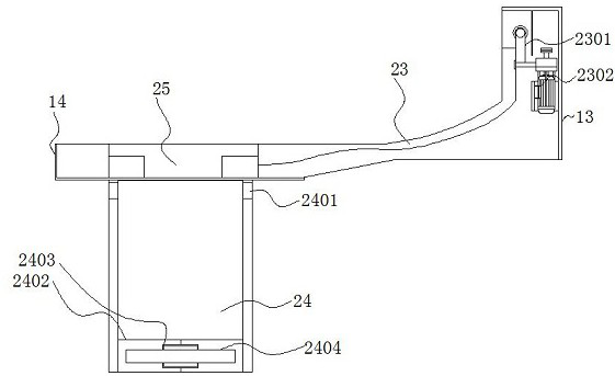
[0030] The left end outside the first detection frame 6 is provided with a stable frame 8 , and the right end outside the first detection frame 6 is installed with a placing frame 11 , the outer right end of the conveyor belt 12 is provided with a connecting accommodating frame 13 , and the inside of the connecting accommodating frame 13 is installed with a connecting frame 13 . The guiding device 23, the guiding device 23 comprises a trachea 2301 and an air pump 2302, and one end inside the guiding device 23 is provided with a tracheal tube 2301, and an outer end of the air tube 2301 is provided with an air pump 2302, the interior of the guiding device 23 is hollow, and the guiding device 23 and the air tube are 2301 is connected, the material of the guide device 23 is rubber and the interior is hollow. After the initial detection is completed, according to the conveying needs of the article, the interaction between the air pump 2302 and the air pipe 2301 can be used to inject an appropriate amount of gas into the interior of the guide device 23 according to the need for conveying the article. The setting of the material of the guiding device 23 can effectively reduce the gravitational damage when the workpiece 1 is dropped when the article is dropped from the conveyor belt 12, and at the same time, the transmission of the workpiece can be conveyed by the amount of gas injected into the guiding device 23. The frequency is adjusted, the structure is simple, the use is flexible, and it is convenient for users to use.
[0031] A guide frame 14 is provided at the end of the guide device 23, and a leakage port 25 is installed in the middle of the guide frame 14. The bottom of the leakage port 25 is provided with a guide connecting device 24. The guide connecting device 24 includes a connecting block 2401, a connecting frame 2402, an electric The push rod 2403 and the push plate 2404 are provided with connecting blocks 2401 at both ends outside the top of the guide connecting device 24, a connecting frame 2402 is installed on the outside of the lower end of the guide connecting device 24, and an electric push rod 2403 is arranged inside the connecting frame 2402. An outer end of the electric push rod 2403 is installed with a push plate 2404, and the push plate 2404 is fixedly connected with the electric push rod 2403, and one end of the outer end of the electric push rod 2403 is connected to the frame 2402 by welding, which guides the connection device 24 to be inclined at an angle. Placement, when the article falls from the inside of the leak 25, it can slide down along the outer surface of the guide connecting device 24, effectively preventing the workpiece 1 from being directly dropped and causing damage, and when the article falls to the bottom of the guide connecting device 24 The position of the push plate 2404 can be moved by the interaction between the connecting frame 2402 and the electric push rod 2403, so that the workpiece 1 can be continuously conveyed, and the interaction between the second detection head 15 and the second camera 16 can be used later. Visual inspection and image capture of items.
[0032] A support frame 20 is installed on the outside of the bottom of the conveyor belt 12 , and a second detection head 15 is installed in the middle of the inner part of the support frame 20 . An auxiliary device 17 is provided. The auxiliary device 17 includes a rotating shaft 1701 and a connecting sleeve plate 1702, and the upper end of the auxiliary device 17 penetrates through the rotating shaft 1701. Both ends outside the rotating shaft 1701 are installed with connecting sleeve plates 1702, and the interior of the connecting sleeve plate 1702 is installed. It is fixedly connected with the rotating shaft 1701, and the middle part outside the rotating shaft 1701 is movably connected with the upper end inside the auxiliary device 17, so that the article can be placed under the second detection head 15 after the initial inspection of the article is completed, and the article can be accurately placed in the second inspection. When the lower surface of the head 15 is located, the auxiliary device 17 can use the interaction between the rotating shaft 1701 and the connecting sleeve 1702 to rotate, so as to prevent the workpiece 1 from entering the entrance below the second detection head 15 to a certain extent. When the workpiece 1 is visually inspected again by the second detection head 15 , the light is scattered, which affects the detection effect of the workpiece 1 . The right end is provided with a collection frame 19, the sorting auxiliary device 18 includes a motor 1801, a transverse cavity 1802, a cooling plate 1803, a sorting plate 1804, a placement cavity 1805, a water pump 1806 and an extension pipe 1807, and the middle of the sorting auxiliary device 18 is provided with a motor 1801 , the outer end of the motor 1801 is provided with a classification plate 1804, the right end of the motor 1801 is provided with a heat dissipation plate 1803, and the outer end of the heat dissipation plate 1803 is connected with a transverse cavity 1802, and the outer end of the transverse cavity 1802 is provided with a placement cavity 1805, the placement cavity A water pump 1806 is installed at one end outside the 1805, and an extension tube 1807 is arranged at one end outside the placement cavity 1805. The extension tube 1807 communicates with the placement cavity 1805, and the interior of the placement cavity 1805 is hollow, and the placement cavity 1805 passes through the water pump 1806 and the horizontal. The cavity 1802 is connected to the heat dissipation plate 1803, and after the secondary visual inspection is completed, some unqualified items can be rejected, and the classification plate 1804 can be rotated by the action of the motor 1801 and the shaft. The rotation can push the workpiece 1 from left to right after detection, which is convenient for sorting and processing the articles, and can utilize the mutual interaction between the transverse cavity 1802, the heat dissipation plate 1803, the placement cavity 1805 and the water pump 1806 during long-term use. The function is to circulate the water between the cooling plate 1803 and the placement cavity 1805. Through the circulation of the water, the heat during the operation of the motor 1801 can be drained in time. After the water circulates for a certain period of time, the extension pipe 1807 can be used. After the water is discharged, it can be used for other purposes. The side collection frame 22 is located at the left end of the outside of the sorting auxiliary device 18, and the side collection frame A cover plate 21 is attached to the inside of the front end of 22 .
[0033] To sum up, the size detection equipment with data acquisition function for computer graphics card processing, when in use, firstly, the user can place the workpiece 1 to be detected on the outer surface of the conveyor belt 12 through the function of the auxiliary feeding frame 3, The conveying belt 12 continues to convey the workpiece 1. The conveying of the conveying belt 12 can cause the workpiece to be conveyed to the bottom of the fixing device 10, and then the distance between the fixing plate 1004 and the movable plate 1005 can be adjusted by the action of the micro air rod 1002. , the height of the fixed plate 1004 and the movable plate 1005 and the conveyor belt 12 can be adjusted by the action of the hydraulic air rod 1001, so that the workpieces placed on the outer surface of the conveyor belt 12 can be clamped and fixed. The structure is simple, the conveyor belt 12 and the fixing device The cooperation between 10 and 10 can effectively improve the detection efficiency of the article. After fixing the workpiece 1, the data detection of the article can be performed by using the setting of the first detection head 7 inside the first detection frame 6. During the detection process, the first detection head 7 can be used. The design of the camera 9 is to collect data images of the items. After the initial detection of the items is completed, the items after the detection are placed outside the conveyor belt 12. When conveyed to the end of the conveyor belt 12, they will fall to the outer surface of the guide device 23. Then, the material of the guiding device 23 is rubber and the interior is hollow. After the initial detection is completed, according to the conveying needs of the article, the interaction between the air pump 2302 and the air pipe 2301 can be used to inject an appropriate amount of gas into the interior of the guiding device 23 according to the conveying needs of the article. The setting of the material of the guide device 23 can effectively reduce the gravitational damage when the workpiece 1 falls when the article falls from the conveyor belt 12, and at the same time, the transmission frequency of the workpiece can be adjusted by the amount of gas injected into the guide device 23. After adjustment, the article will continue to be conveyed, and the placement of the guide connecting device 24 at an inclination angle can slide down along the outer surface of the guide connecting device 24 when the article falls from the inside of the leak 25, effectively preventing the workpiece 1 from being directly When the drop causes damage, when the item falls to the bottom of the guide connecting device 24, the position of the push plate 2404 can be moved by the interaction between the connecting frame 2402 and the electric push rod 2403, so that the workpiece 1 can be continuously conveyed. It is convenient to use the interaction between the second detection head 15 and the second camera 16 to perform visual inspection and image capture of the article. The visual inspection method can detect the size and shape of the workpiece 1. After the secondary visual inspection is completed, some items with unqualified sizes are removed, and the classification plate 1804 can be rotated by the action of the motor 1801 and the shaft. Push to the right, the qualified items will be pushed to the inside of the collection frame 19, and the unqualified items will be pushed to the inside of the side collection frame 22, which is convenient for subsequent users to uniformly process the workpiece 1, and thus completes the entire computer graphics card. The process of using the dimensional inspection equipment with data acquisition function for processing.
[0034] The above are only preferred specific embodiments of the present invention, but the protection scope of the present invention is not limited thereto. Equivalent replacements or changes to the inventive concept shall all fall within the protection scope of the present invention.