
Symmetrical double-side-driven vertical lifting wave buoy calibrating device

A wave buoy, double-sided drive technology, applied in the field of verification, can solve the problems of random waves, safety accidents, and inability to change

Pending Publication Date: 2021-07-27
NAT CENT OF OCEAN STANDARDS & METROLOGY
View PDF0 Cites 1 Cited by
  • Summary
  • Abstract
  • Description
  • Claims
  • Application Information

AI Technical Summary

Problems solved by technology

[0005] However, when using the rotating sine analog verification device to verify the wave buoy, after the buoy is installed and fixed, its position cannot be changed during the rotation process, that is, the wave height cannot be adjusted at any time, because the counterweight cannot be adjusted accordingly during the rotation process.
If there is a weight imbalance on both sides of the central axis of rotation of the truss, serious safety accidents will occur
Secondly, the rotary sine simulation verification device can only simulate regular and standard sine waves in the vertical direction, but the waves are not regular sine waves in real sea conditions, and the wave height and wave period of each wave will change with time. waves are random
This type of verification device cannot meet the requirements of wave buoys for measuring performance of random wave height and wave period.
In addition, the function of the rotating sine analog verification device is relatively single, and it can only be used to measure accelerometer-type wave buoys, and cannot meet the calibration of wave measuring instruments or sensors based on other acoustic and optical principles.

Method used


Image

  • Symmetrical double-side-driven vertical lifting wave buoy calibrating device
  • Symmetrical double-side-driven vertical lifting wave buoy calibrating device
  • Symmetrical double-side-driven vertical lifting wave buoy calibrating device

Examples


Embodiment Construction

[0017] In order to facilitate the understanding of the present invention, the embodiments of the present invention will be described below in conjunction with the accompanying drawings. Those skilled in the art should understand that the following description is only for the convenience of explaining the present invention, not as a specific limitation on its scope.

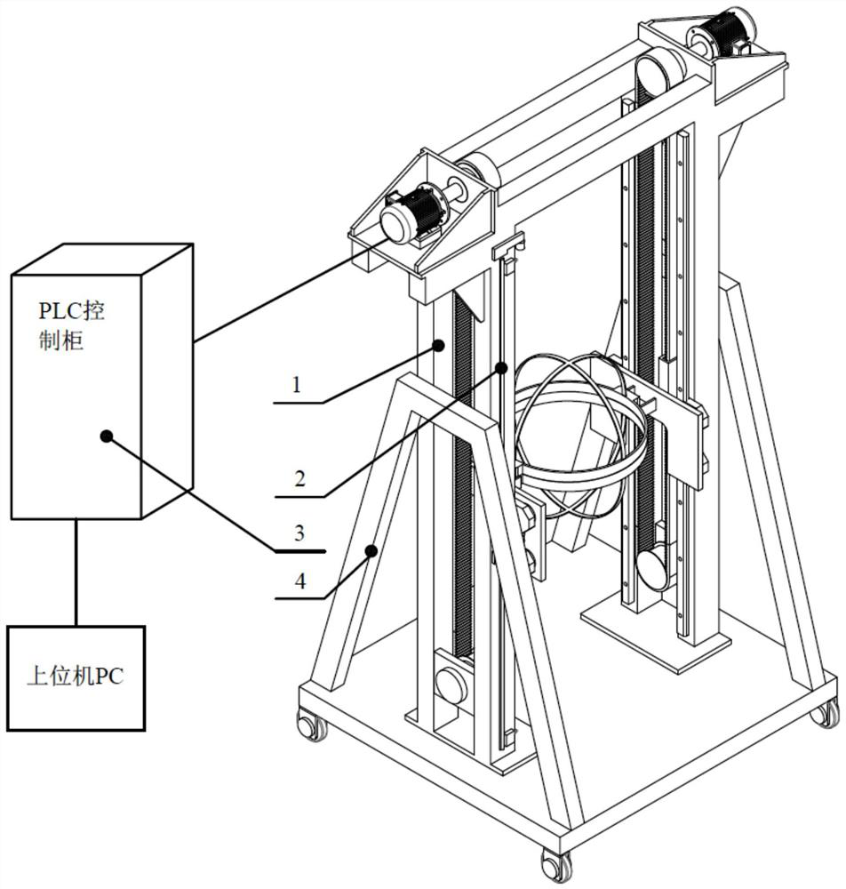
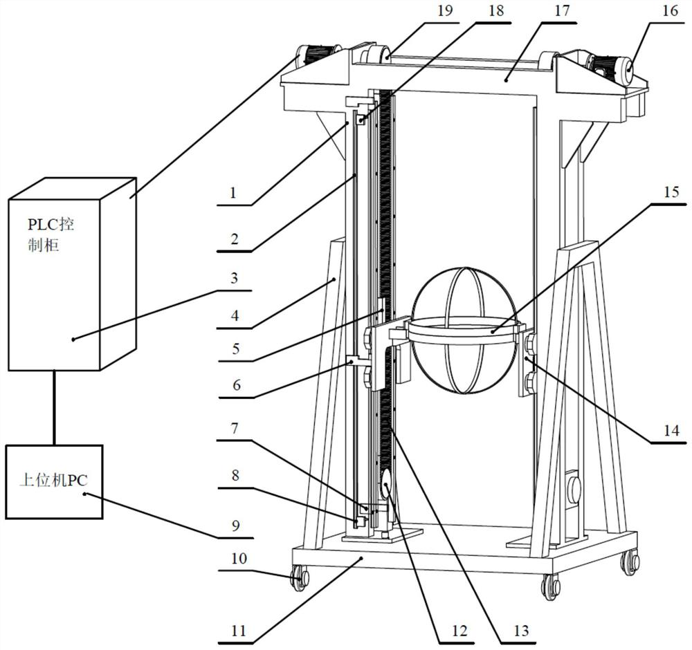
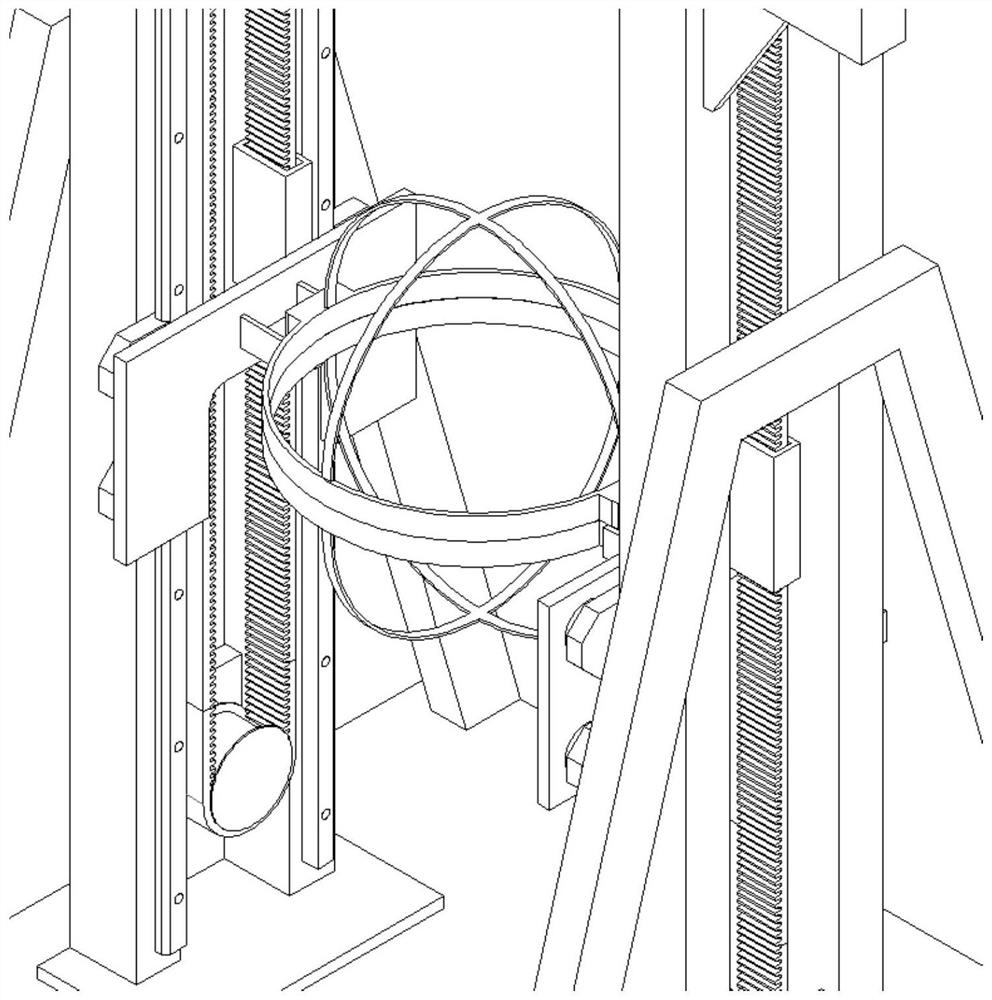
[0018] The invention provides a symmetrical double-sided driving vertical lifting wave buoy verification device, such as figure 1 As shown, the testing device includes:

[0019] The main frame, the main frame includes a main column 1, the main column 1 is a left-right symmetrical structure, and the left main column and the right main column are arranged at a predetermined distance;

[0020] Chassis 11, four Fuma wheels 10 are installed on the bottom of the chassis 11, and the four Fuma wheels 10 support the chassis; the main frame is arranged on the chassis 11, and the main frame The frame is located on the upper...


PUM


Abstract

The invention provides a symmetrical double-side-driven vertical lifting wave buoy calibrating device which comprises a main frame, a motor driving system, a wave buoy fixture system and a displacement measurement and control limiting system, wherein the main frame comprises a main body stand column, the main body stand column is a left-right symmetrical structure, and the left main body stand column and the right main body stand column are arranged at a preset interval; the motor driving system comprises a first motor driving system and a second motor driving system, the first motor driving system is matched with the left main body stand column, and the second motor driving system is matched with the right main body stand column; the wave buoy fixture system comprises a first fixture sliding table frame, a second fixture sliding table frame and a wave buoy fixture; and the displacement measurement and control limiting system is used for controlling the moving position of the wave buoy fixture system. A symmetrical double-side-driven structure is adopted, the phenomenon of uneven loads does not exist, the device operates stably, the balance weight does not need to be adjusted in the whole wave simulation process, and the wave buoy can keep a vertical upward posture all the time.

Description

technical field [0001] The invention relates to the verification field, in particular to a symmetrical double-side driven vertical lifting wave buoy verification device. Background technique [0002] Waves are one of the basic elements of marine hydrological observation. Wave buoy is one of the main equipments for long-term, regular and fixed-point observation of waves at present. It floats on the sea surface and tracks the trajectory of waves. It can measure the wave height and wave period of ocean waves, and some can also measure the wave direction. Metrological verification of the measurement results of wave buoys to ensure the accuracy and reliability of the measurement values ​​is an important measure to ensure the effectiveness of wave observation. [0003] At present, measurement or scientific research institutions at home and abroad have developed measurement devices for verifying wave buoys in laboratories. Some make waves in a towed tank, but this verification m...

Claims


Application Information

Patent Timeline
IPC IPC(8): G01C25/00
CPCG01C25/00
Inventor 于建清贾伟广秦鑫培朱丽萍
Owner NAT CENT OF OCEAN STANDARDS & METROLOGY
Learn More