Circular ring-shaped slit emitter and manufacturing method thereof

A slit-type, emitter technology, applied in cold cathode manufacturing, electrode system manufacturing, discharge tube/lamp manufacturing, etc., can solve the problem of excessive electric field strength at the tip of the end face, improve work efficiency and life, and have a simple structure , Improve the effect of thrust range

Inactive Publication Date: 2021-07-27
SUN YAT SEN UNIV
View PDF2 Cites 0 Cited by
  • Summary
  • Abstract
  • Description
  • Claims
  • Application Information

AI Technical Summary

Problems solved by technology

[0004] The purpose of the present invention is to provide a circular slit emitter and its manufacturing method to solve the problem of edge-priority emission caused by the excessive electric field intensity at the tip of the end face

Method used


Image

  • Circular ring-shaped slit emitter and manufacturing method thereof
  • Circular ring-shaped slit emitter and manufacturing method thereof

Examples


Embodiment Construction

[0024] The following will clearly and completely describe the technical solutions in the embodiments of the present invention with reference to the accompanying drawings in the embodiments of the present invention. Obviously, the described embodiments are only some, not all, embodiments of the present invention. Based on the embodiments of the present invention, all other embodiments obtained by persons of ordinary skill in the art without creative efforts fall within the protection scope of the present invention.

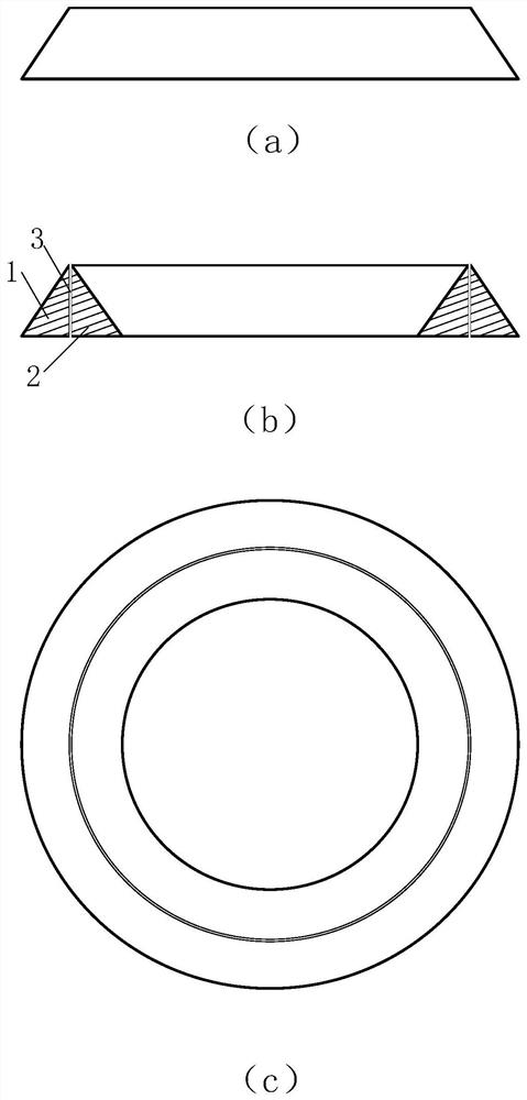
[0025] Due to the discovery of the disadvantages of the traditional emitter having a very small single-needle thrust of the capillary emitter, a large number of capillary emitters need to be integrated to obtain the thrust required by the task; the ribbed and blade-shaped slit emitters have the electric field strength at both ends of the tip If it is too large, it will lead to the problem of inconsistent emission; if the emitter of porous material is used, it is dif...


PUM

PropertyMeasurementUnit
Widthaaaaaaaaaa

Abstract

The invention discloses a circular ring-shaped slit emitter and a manufacturing method thereof, and relates to the technical field of space electric propulsion. The circular ring-shaped slit emitter comprises a circular ring body, and the cross-sectional area of the circular ring body is gradually reduced from the bottom to the top. The circular ring body comprises an outer ring assembly and an inner ring assembly, and a slit exists between the outer ring assembly and the inner ring assembly. According to the present invention, a working medium is supplied to the circular ring-shaped slit emitter, and an electric field is applied to the emitter, so that the working medium forms a Taylor cone at the tip of the emitter, the electric field intensity is further increased, and the emitter can form multi-point emission. The radius of curvature of each tip of the circular ring-shaped emitter is equal, and no end face exists, so that the tip has no electric field intensity concentration, and emission inconsistency is avoided. The emission point density can be changed by adjusting the radius of the emitter and parameters between an extraction electrode and the emitter.

Description

technical field [0001] The invention relates to the technical field of space electric propulsion, in particular to an annular slit emitter and a manufacturing method thereof. Background technique [0002] Field emission generates a charged particle beam by applying an electric field force to the working fluid in the emitter. Since the thrust of the traditional needle emitter is extremely small, multiple emitter arrays are required to increase the thrust. The integrated manufacturing of multiple emitters can improve the thruster efficiency, but integrating too many emitters in a small area will cause mutual interference of emitters and space charge accumulation. In addition, due to the small size of the emitter, precise assembly of the extractor is very difficult. [0003] The radius of curvature of the emitter tip is one of the main factors affecting field emission. The emitters such as ribbed and blade-shaped emitters have large curvature radii on both sides, resulting in ...

Claims


Application Information

Patent Timeline
IPC IPC(8): H01J1/304H01J9/02F03H1/00
CPCH01J1/304H01J9/025F03H1/0087
Inventor 沈岩杨铖彭惠生陈全
Owner SUN YAT SEN UNIV
Why Eureka
Try Eureka