Chain used for conveyor belt type dump semi-trailer

A technology for conveyor belts and semi-trailers, which is applied to conveyors, conveyor objects, vehicles with endless chains/belts, etc., can solve the problem of aggravating the wear between chain parts and sprockets, long oil supply time, and polluting the environment. and other problems, to achieve the effect of slowing down the impact of the bite, improving work efficiency and life.

Active Publication Date: 2020-09-11
LUDONG UNIVERSITY
View PDF15 Cites 2 Cited by
  • Summary
  • Abstract
  • Description
  • Claims
  • Application Information

AI Technical Summary

Problems solved by technology

The artificial oiling of the prior art is often uneven, which is prone to grease dripping and pollutes the environment; in addition, the grease on the surface of the chain is easily contaminated with dust and forms sludge, which intensifies the friction between the chain parts and between the chain and the sprocket. Wear and tear, also pollute the environment
At present, there are many kinds of automatic oiling devices; the utility model patent with application number 201520453923.2 proposes an automatic oiling and maintenance device for the chain of automobile production line equipment, which can automatically oil and maintain when the equipment is running, which can achieve average oil supply and ensure equipment maintenance It is more effective; thi

Method used


Image

  • Chain used for conveyor belt type dump semi-trailer
  • Chain used for conveyor belt type dump semi-trailer
  • Chain used for conveyor belt type dump semi-trailer

Examples


Embodiment Construction

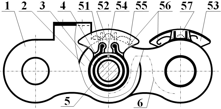
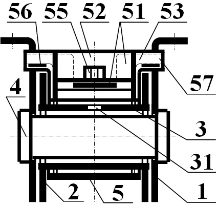
[0058] The technical solution of the present invention will be described in detail below in conjunction with the accompanying drawings and specific embodiments. figure 1 It is the front view of the chain of the present invention, figure 2 For the chain of the present invention in figure 1 The right side view of the position; the chain of the present invention includes an outer link plate 1 , an inner link plate 2 , a sleeve 3 , a pin shaft 4 and a roller 5 . The outer chain plate 1, the inner chain plate 2 and the pin shaft 4 are preferably the structure, size and connection relationship of the conveyor chain in the prior art.

[0059] The sleeve 3 is a cylindrical structure with a through hole 31 in the middle of the upper side; the through hole 31 is preferably formed by cutting. The outer chain plate 1 , the inner chain plate 2 , the sleeve 3 and the pin shaft 4 are preferably processed and formed using the metal material and production process of the conveyor chain in t...


PUM


Abstract

The invention relates to a chain used for a conveyor belt type dump semi-trailer, and belongs to the technical field of chains and dump semi-trailers. A roller of the chain comprises a rolling cylinder, an oil storage cylinder, end covers and a pressing plate. The oil storage cylinder is positioned at the upper side of the rolling cylinder and communicates with the rolling cylinder; the oil storage cylinder is provided with a side opening; and the oil storage cylinder is filled with elastic porous oil-absorption material and used for storing lubricating oil, so that a sleeve and a pin shaft are well lubricated. The lubricating oil is filled into the side opening through an upper oil wheel; and the side opening can be automatically closed to avoid leakage of the lubricating oil and preventthe outer surface of the chain and the environment from being polluted. The end covers are positioned at the front and rear sides of the rolling cylinder and the oil storage cylinder; and the end covers elastically abut against inner chain plates so as to close the roller relative to the inner chain plates, so that the aggravation of abrasion and corrosion due to the invasion of dust and water canbe avoided. The pressing plate elastically abuts against the inner chain plates or an outer chain plate at the left and right ends so as to limit the rotation range of the rolling cylinder, ensure that the rolling cylinder can automatically return to the original position and maintain the relative position, reduce the meshing impact, and prolong the service life. The upper oil wheel of the chainis capable of controlling the circulation of the lubricating oil, avoiding leakage and preventing pollution.

Description

technical field [0001] The invention relates to a chain, in particular to a chain for a self-unloading semi-trailer, and belongs to the technical field of chains and self-unloading semi-trailers. Background technique [0002] The conveyor belt self-unloading semi-trailer has the advantages of fast unloading, large loading, high safety and easy operation, and also avoids the easy rollover, space limitation, easy burying of tires and easy deformation of the box board of the back-turning and side-turning self-unloading semi-trailer The shortcomings have been promoted and applied. The conveyor chain of the conveyor belt self-unloading semi-trailer needs to transport bulk cargo during unloading, and bears the tension, so the roller conveyor chain is used. The chain is composed of five parts: inner chain plate, outer chain plate, pin shaft, sleeve and roller. The outer chain plate is fixed on the pin shaft, the inner chain plate is fixed on the sleeve, the roller and the sleeve a...

Claims


Application Information

Patent Timeline
IPC IPC(8): B65G45/08B65G17/40B60P1/36
CPCB60P1/36B65G17/40B65G45/08
Inventor 苏子林林红旗赵万胜李勃宁
Owner LUDONG UNIVERSITY
Why Eureka
Try Eureka