
Mechanical connecting rod mechanism

A connecting rod mechanism and connecting rod technology, applied in the field of mechanical connecting rod mechanism, can solve the problems of unrealized mechanical connecting rod mechanism, inconvenient maintenance, large size of seeder, etc.

Inactive Publication Date: 2021-07-30
SHANDONG VOCATIONAL COLLEGE OF SCI & TECH
View PDF0 Cites 0 Cited by
  • Summary
  • Abstract
  • Description
  • Claims
  • Application Information

AI Technical Summary

Problems solved by technology

[0002] Currently known seeding machines, such as corn planters, peanut planters, garlic planters, etc., in order to achieve single-grain seeding, often adopt the principles of spoon wheel type, air suction type, etc., but the above two seeding principles need to be matched. Corresponding accessories, such as spoon wheel seed meter, fan, etc.
[0003] However, in the prior art, the joint work of the whole set of sowing machinery has not been realized through the mechanical linkage mechanism on the above-mentioned machinery, and most of the auxiliary devices in the prior art lead to the large size of the sowing machine, high cost, and inconvenient maintenance. It is difficult to apply to small and medium-sized seeders. The existing small and medium-sized seeders have not realized the drive of the seed scoop through the mechanical linkage mechanism to control the extension length of the seed scoop, so as to accurately adjust the sowing quantity of the sowing machine
[0004] In summary, there are obviously inconveniences and defects in the actual use of the existing technology, so it is necessary to improve

Method used


Image

  • Mechanical connecting rod mechanism
  • Mechanical connecting rod mechanism
  • Mechanical connecting rod mechanism

Examples


Embodiment Construction

[0031] In order to make the purpose, technical solution and advantages of the present invention clearer, the present invention will be further described in detail in conjunction with the accompanying drawings and the application of the mechanical linkage mechanism on seeding machinery as an example; wherein, the spoon device in the present invention is Based on the characteristics defined by the application on the seeding machine, the spoon seeder is the output end of the mechanical linkage mechanism, which can be replaced with other components according to the application scenario. It should be understood that the specific embodiments described here are only used to explain the present invention, not to limit the present invention.

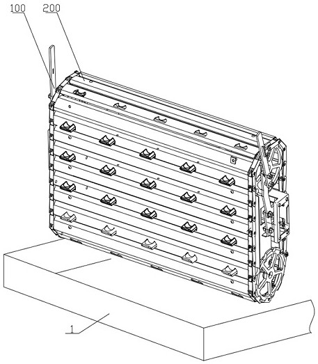
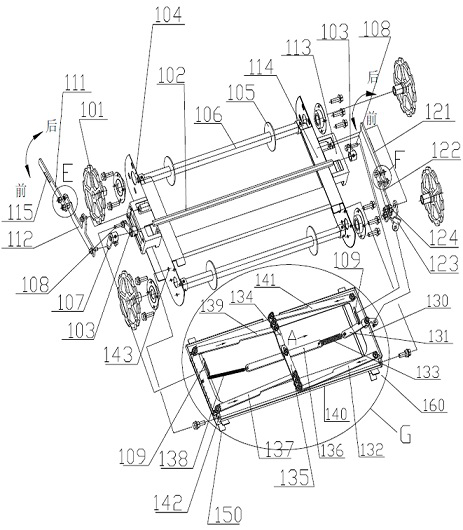
[0032] see figure 1 , a mechanical linkage mechanism, comprising a linkage adjustment mechanism combination 100 and a linkage transmission track combination 200.

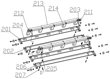
[0033] see figure 2 , The connecting rod transmission track assembly 200 includes...


PUM


Abstract

The invention belongs to the technical field of mechanical connecting rods, and particularly relates to a mechanical connecting rod mechanism. The mechanical connecting rod mechanism comprises a rotating connecting rod mechanism, a first connecting rod adjusting mechanism and a connecting rod transmission track combination. The rotating connecting rod mechanism comprises a rotating assembly arranged on a first connecting rod support and used for driving the connecting rod transmission track combination to rotate. The first connecting rod adjusting mechanism comprises a second connecting rod support rotationally connected with the first connecting rod support, a sliding assembly is fixedly connected with a first handle combination and rotationally connected with the first connecting rod support, and a sliding rail assembly is arranged on the second connecting rod support. The connecting rod transmission track combination comprises a plurality of track assemblies and a plurality of output end mounting assemblies, and the track assemblies and the output end mounting assemblies are annularly connected. Therefore, a first handle is in transmission connection with the output end, the first handle is adjusted to change the change of the transmission length of the output end, and the purpose of accurately adjusting the extension length of the output end is achieved.

Description

technical field [0001] The invention belongs to the technical field of seeders, and in particular relates to a mechanical linkage mechanism. Background technique [0002] Currently known seeding machines, such as corn planters, peanut planters, garlic planters, etc., in order to achieve single-grain seeding, often adopt the principles of spoon wheel type, air suction type, etc., but the above two seeding principles need to be matched. Corresponding accessories, such as spoon wheel seed meter, fan, etc. [0003] However, in the prior art, the joint work of the whole set of sowing machinery has not been realized through the mechanical linkage mechanism on the above-mentioned machinery, and most of the auxiliary devices in the prior art lead to the large size of the sowing machine, high cost, and inconvenient maintenance. It is difficult to apply to small and medium-sized seeders. The existing small and medium-sized seeders have not realized the drive of the seed scoop through...

Claims


Application Information

Patent Timeline
IPC IPC(8): A01C7/18A01C7/20
CPCA01C7/18A01C7/20
Inventor 季有昌李东卫
Owner SHANDONG VOCATIONAL COLLEGE OF SCI & TECH
Learn More