Dynamic seal method and seal device of sintering pallet bottom and air box separated beam

A technology of sealing device and machine trolley, which is applied in the direction of engine sealing, mechanical equipment, engine components, etc., can solve the contradiction between the undertray and sealing of the trolley, the difficulty in controlling the negative pressure of the bellows ignition, Problems such as the increase of negative pressure of ignition and ventilation can achieve the effects of reducing ignition energy consumption, saving ignition fuel, and reducing negative pressure of ignition and ventilation

Inactive Publication Date: 2009-05-20
ANSTEEL GRP MINING CO LTD
View PDF0 Cites 10 Cited by
  • Summary
  • Abstract
  • Description
  • Claims
  • Application Information

AI Technical Summary

Problems solved by technology

If there is not enough clearance between the bottom beam of the trolley body and the fixed bellows partition beam, the trolley will easily collide with the fixed partition beam when moving, causing equipment accidents, affecting production, and causing certain economic losses
However, the existence of this gap makes it difficult to control the negative pressure of the ignition and ventilation of the bellows under the ignition furnace, because the remaining gap will cause cross-flow between the bellows, resulting in an increase in the negative pressure of the ignition and ventilation, and the consumption of ignition fuel. produce
[0003] At present, there are many ways to seal between the trolley and the bellows. Most of the sealing devices and the trolley body are sealed with wire seals. less than good sealing effect

Method used


Image

  • Dynamic seal method and seal device of sintering pallet bottom and air box separated beam
  • Dynamic seal method and seal device of sintering pallet bottom and air box separated beam
  • Dynamic seal method and seal device of sintering pallet bottom and air box separated beam

Examples


Embodiment 2

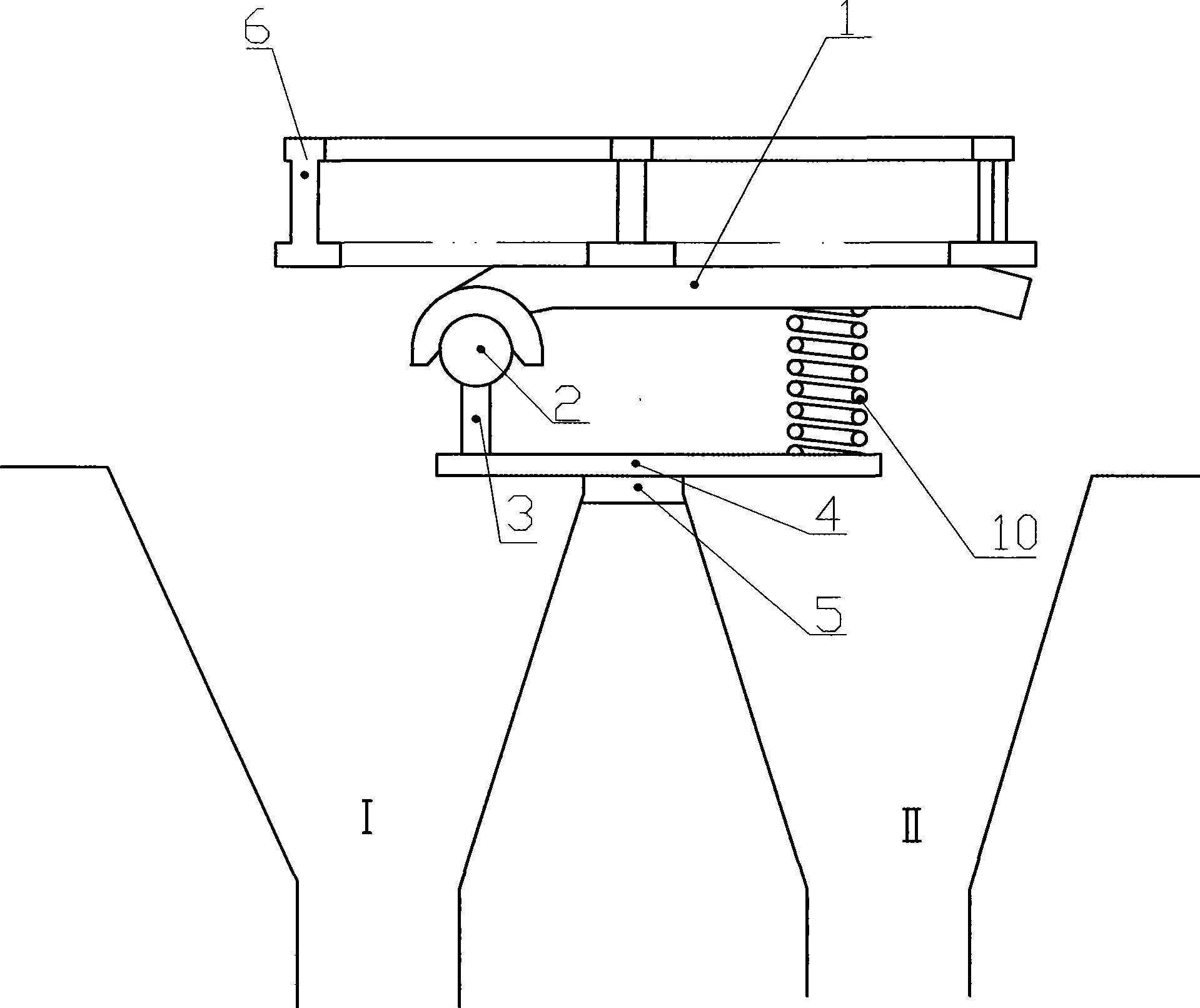
[0018] Embodiment 2 (see attached figure 2 ): the sealing cover plate 1 located under the bottom beam of the trolley is fixed on the bottom plate 4 through the pressure spring 10, and the bottom plate 4 is connected with the bellows partition beam 5; Positioned thrust stop iron 8; a flexible sealing plate 9 is arranged at the middle position between the sealing cover plate and the bottom plate. The spring force pushes up the sealing cover plate 1 and makes close contact with the bottom surface of the trolley beam to achieve the purpose of sealing and isolation. Thrust stopper 8 positions the sealing plate and allows space to move up and down.

Embodiment 3

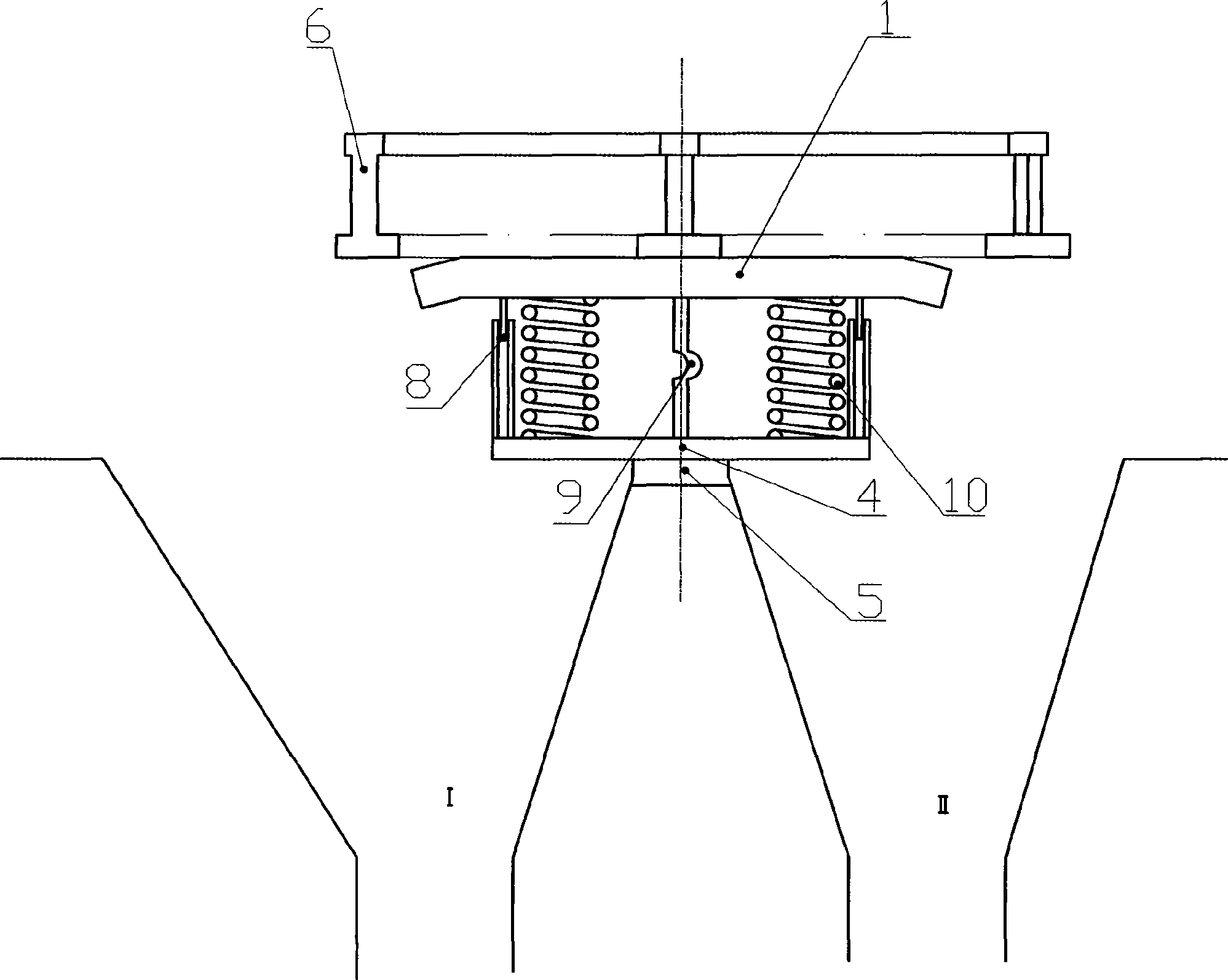
[0019] Embodiment 3 (see attached image 3 ): There is a semicircular groove under one end of the sealing cover plate 1, the groove is movably connected with the supporting shaft 2, the supporting shaft 2 is installed on one end of the bottom plate 4 through the vertical plate 3, and the bottom plate 4 is connected with the bellows partition beam 5; the sealing cover A compression spring 10 is arranged between the plate and the other end of the bottom plate. The other end of the sealing cover plate 1 is lifted up under the action of the elastic force of the spring, and contacts with the bottom surface of the trolley body crossbeam, realizing the effective sealing between the two bellows connecting partition beams and the bottom of the trolley body crossbeam.


PUM


Abstract

The invention relates to a method for dynamic sealing between the bottom of a trolley of a sintering machine and an isolation beam of a blower and a sealing device thereof and belongs to the field of sintering equipment in the ferrous metallurgy industry. The invention is developed aiming at the problem of the sealing between a connecting part of two blowers on the lower part of an ignition furnace of the prior belt-type sintering machine and the bottom of a crossbeam of a trolley body of the sintering machine is poor so as to cause easy air crossing. A sealing device with a sealing cover plate is arranged between the connecting isolation beam of two blowers of the sintering machine and the bottom of the crossbeam of the trolley body; the lower part of the sealing device is connected with the isolation beam of the blowers; and the upper surface of the cover plate of the sealing device is tightly contacted with the plane of the crossbeam on the bottom of the trolley through gravity or spring force, thereby achieving the dynamic sealing between the connecting part of the two blowers and the bottom of the crossbeam of the trolley body of the sintering machine. The sealing device has the characteristics that the sealing device has good dynamic sealing performance and no air crossing and prevents the trolley body from downwarping, can be used for the sealing between the trolleys of the machine head and the machine tail of the belt-type sintering machine and the blower and can be also used for the sealing between a middle trolley body of the sintering machine and the blower.

Description

technical field [0001] The invention belongs to the field of sintering equipment in the iron and steel metallurgical industry, and mainly relates to a dynamic sealing method and a sealing device for preventing the crosswind of the bellows of the sintering machine and maintaining the stability of the wind pressure. Background technique [0002] Between the connection of the two bellows below the ignition furnace of the belt sintering machine and the bottom of the crossbeam of the sintering machine trolley, a fixed partition beam is designed to reduce the cross-wind of the bellows. From the top of the bellows partition beam to the bottom beam of the trolley body, generally There is a certain gap. The sintering machine trolley carries a certain weight of material. Under the action of the negative pressure of the draft and the self-weight of the trolley body, the trolley is subjected to a downward force. After a long time of use, some trolley bodies will have a certain amount o...

Claims


Application Information

Patent Timeline
Patent Type & Authority Applications(China)
IPC IPC(8): F27B21/08F16J15/00
Inventor 王常秋段志达郝振芳郭宪辉
Owner ANSTEEL GRP MINING CO LTD
Why Eureka
Try Eureka