Stamping system for pneumatic liquid pump production

A liquid pump and pneumatic technology, which is applied in the field of stamping systems for the production of pneumatic liquid pumps, and can solve problems such as component deformation

Inactive Publication Date: 2021-07-30
安徽士必达液压器材有限公司
View PDF0 Cites 3 Cited by
  • Summary
  • Abstract
  • Description
  • Claims
  • Application Information

AI Technical Summary

Problems solved by technology

[0004] The invention proposes a stamping system for the production of pneumatic hydraulic pumps, which solves the problem that the stamping devices for the production of pneumatic hydraulic pumps in the prior art are easily limited and deformed after the parts are fixed.

Method used


Image

  • Stamping system for pneumatic liquid pump production
  • Stamping system for pneumatic liquid pump production
  • Stamping system for pneumatic liquid pump production

Examples


Embodiment Construction

[0032] The following will clearly and completely describe the technical solutions in the embodiments of the present invention with reference to the accompanying drawings in the embodiments of the present invention. Obviously, the described embodiments are only some, not all, embodiments of the present invention.

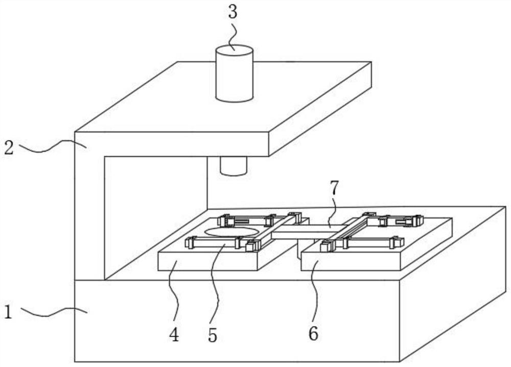
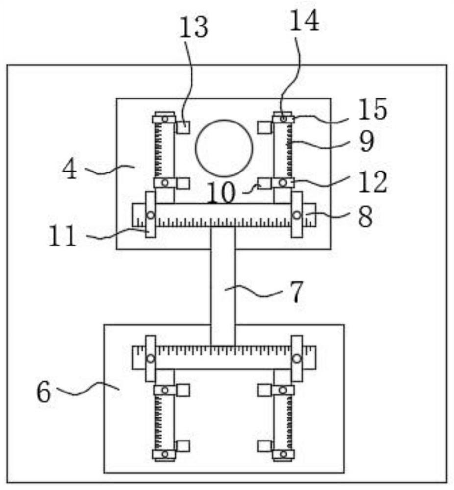
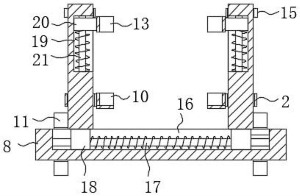
[0033] refer to Figure 1-6 , a stamping system for the production of pneumatic hydraulic pumps, including:

[0034] Processing table 1, processing table 1 is a hollow structure, the top of processing table 1 is installed with mold 4 and punching head 3 matching with mold 4, the top of processing table 1 is installed with mounting frame 2, and punching head 3 is installed on mounting frame 2 On, the stamping head 3 is located directly above the mold 4 to cooperate with the mold 4;

[0035] The feeding mechanism includes a connecting plate 7 and a fixing mechanism 5 installed at both ends of the connecting plate 7. The fixing mechanism 5 includes a horizontal plate 8...


PUM


Abstract

The invention relates to the technical field of pneumatic liquid pump production, in particular to a stamping system for pneumatic liquid pump production, and aims to solve the problems that a stamping device for pneumatic liquid pump production in the prior art is prone to being limited after parts are fixed, and the parts are deformed. According to the technical scheme, the stamping system comprises a machining table of a hollow structure, wherein the top of the machining table is provided with a die and a punching head matched with the die; and a feeding mechanism, wherein the feeding mechanism comprises a connecting plate and fixing mechanisms installed at the two ends of the connecting plate, each fixing mechanism comprises a transverse plate fixed to one end of the connecting plate, two movable plates installed on one side of the transverse plate, a positioning frame and a fixing frame, and the positioning frames and the fixing frames are installed on the sides, close to each other, of the two movable plates. The stamping system for pneumatic liquid pump production is reasonable in structure and easy to operate, parts can be conveniently fixed during stamping, the parts cannot be restrained when the parts deform during stamping, and therefore part stamping is more accurate, and the stamping system is easy to use and popularize.

Description

technical field [0001] The invention relates to the production field of pneumatic liquid pumps, in particular to a stamping system for the production of pneumatic liquid pumps. Background technique [0002] During the production of pneumatic hydraulic pumps, many parts need to be processed by stamping devices. At present, the stamping device used for processing pneumatic hydraulic pumps needs to fix the processed parts before stamping them, so that the parts will not deviate during stamping. [0003] However, the current mechanism used to fix the parts cannot change with the deformation of the parts after the parts are fixed, so that the parts will be restricted by the fixing mechanism in the process of stretching or deformation, thus giving It will affect the quality of parts processing. For this reason, this proposal proposes a stamping system for the production of pneumatic hydraulic pumps. Contents of the invention [0004] The invention proposes a stamping system fo...

Claims


Application Information

Patent Timeline
Patent Type & Authority Applications(China)
IPC IPC(8): B21D22/02B21D37/10B21D43/00B21D43/14
CPCB21D22/02B21D37/10B21D43/003B21D43/14
Inventor 石春炳薛道应朱治国姚志祥
Owner 安徽士必达液压器材有限公司
Why Eureka
Try Eureka