

Self-sealing loading unit and open type load box structure based on self-sealing loading unit
A loading unit and self-sealing technology, which is applied in basic structure engineering, basic structure test, construction, etc., can solve the problems of complex structure, stability, poor sealing, etc., to ensure stability and reliability, and realize self-sealing effect , Improve the efficiency of production and installation
Pending Publication Date: 2021-07-30
ZHEJIANG OUGAN MASCH CO LTD
View PDF6 Cites 0 Cited by
- Summary
- Abstract
- Description
- Claims
- Application Information
AI Technical Summary
Problems solved by technology
The existing loading unit is an oil cylinder type loading
Method used
View moreImage
Smart ImageViewing Examples

Examples
 PUM
 Abstract
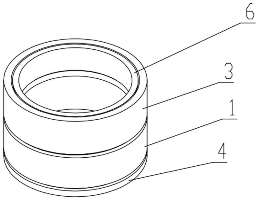
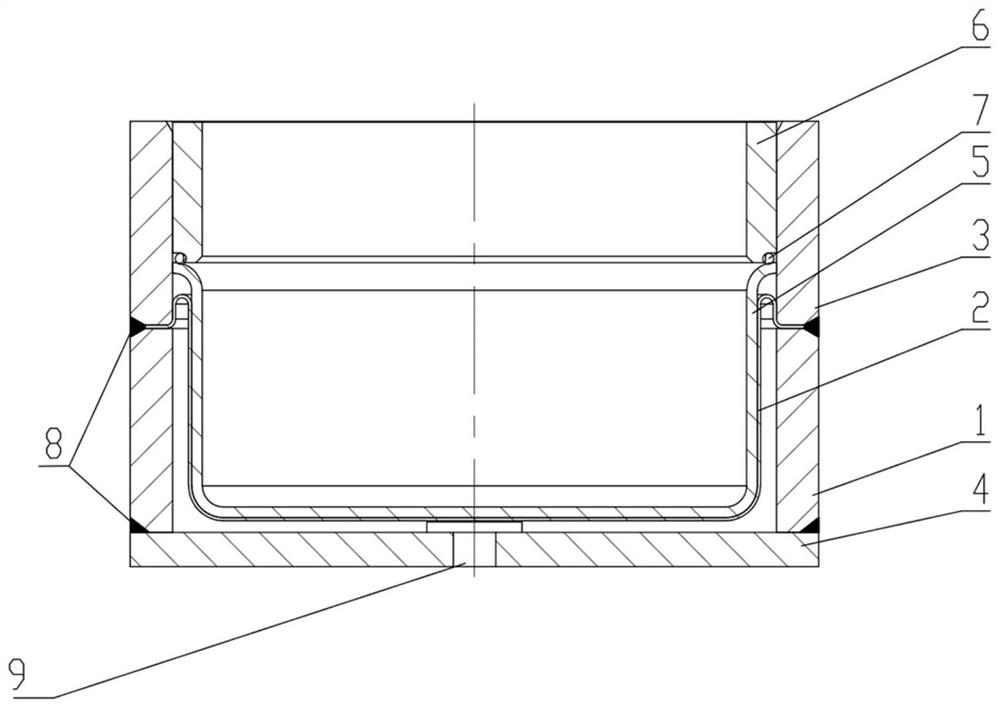
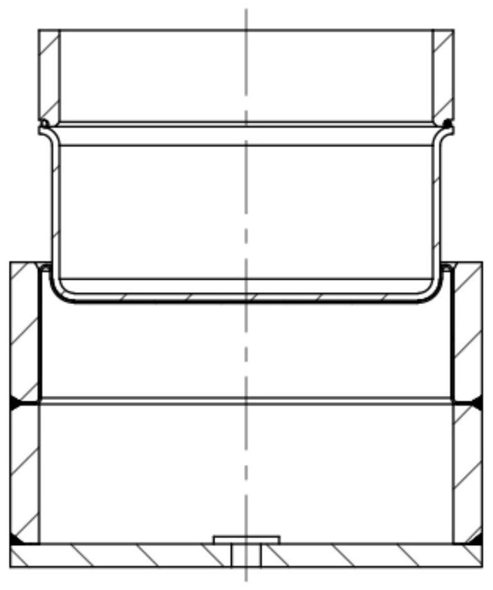
The invention discloses a self-sealing loading unit and an open type load box structure based on the self-sealing loading unit. According to the self-sealing loading unit and the open type load box structure based on the self-sealing loading unit, an upper steel sleeve and a lower steel sleeve are welded, a bottom plate is welded to the bottom face of the lower steel sleeve, a sealing ring is arranged above the bottom plate, the edge of the sealing ring is arranged between the upper steel sleeve and the lower steel sleeve, the upper steel sleeve, the lower steel sleeve, the sealing ring and the bottom plate are combined to form a loading cavity, a lining is placed above the sealing ring, the bottom face of the lining is connected with the sealing ring, the sealing ring moves up and down to enable the loading cavity to ascend or descend, the lining is driven to ascend or descend, loading units, upper base plates installed above the loading units and lower base plates installed below the loading units are combined into loading unit assemblies, the multiple loading unit assemblies are annularly arranged, and reinforcing rings are welded to the upper portions and the lower portions of the loading unit assemblies. According to the self-sealing loading unit, the working stability of the loading units is improved, the modular structure of the open type load box is realized, the production and installation efficiency of the load box is improved, and the working stability and reliability of the load box in a self-balancing static load test system are ensured.
Description
technical field [0001] The invention relates to the field of static load detection of self-balancing pile foundations, in particular to a self-sealing loading unit and an open load box structure based on the unit. Background technique [0002] Self-balancing pile foundation static load detection technology is a static load test pile method in which the weight of the pile itself provides the reaction force without external force. During the construction process, the load box shaped according to the pile bearing capacity parameters is placed in the At the bottom of the pile body, connect the pressure oil pipe and the displacement measuring device to the top of the pile. After the concrete is cured to the standard age, pressurize the bottom load box through the top high-pressure oil pump to obtain the pile end bearing capacity and the total friction resistance of the pile side. At present, with the application and popularization of self-balancing pile foundation static load det...
Claims
Login to View More Application Information
Patent Timeline
 IPC IPC(8): E02D33/00
CPCE02D33/00
Inventor张自平符磊王磊冯校楠马良
OwnerZHEJIANG OUGAN MASCH CO LTD