Method for determining yaw angle of wind rotor by employing unmanned aerial vehicle
A determination method and yaw angle technology, applied in unmanned aerial vehicle, wind turbine monitoring, engine and other directions, can solve the problems of complex operation, large error, low efficiency, etc., achieve high measurement accuracy, increase equipment cost, Wide range of effects
- Summary
- Abstract
- Description
- Claims
- Application Information
AI Technical Summary
Problems solved by technology
Method used
Image
Examples
Embodiment 1
[0057] A method for determining the yaw angle of a wind rotor by using an unmanned aerial vehicle provided by the present invention comprises the following steps:
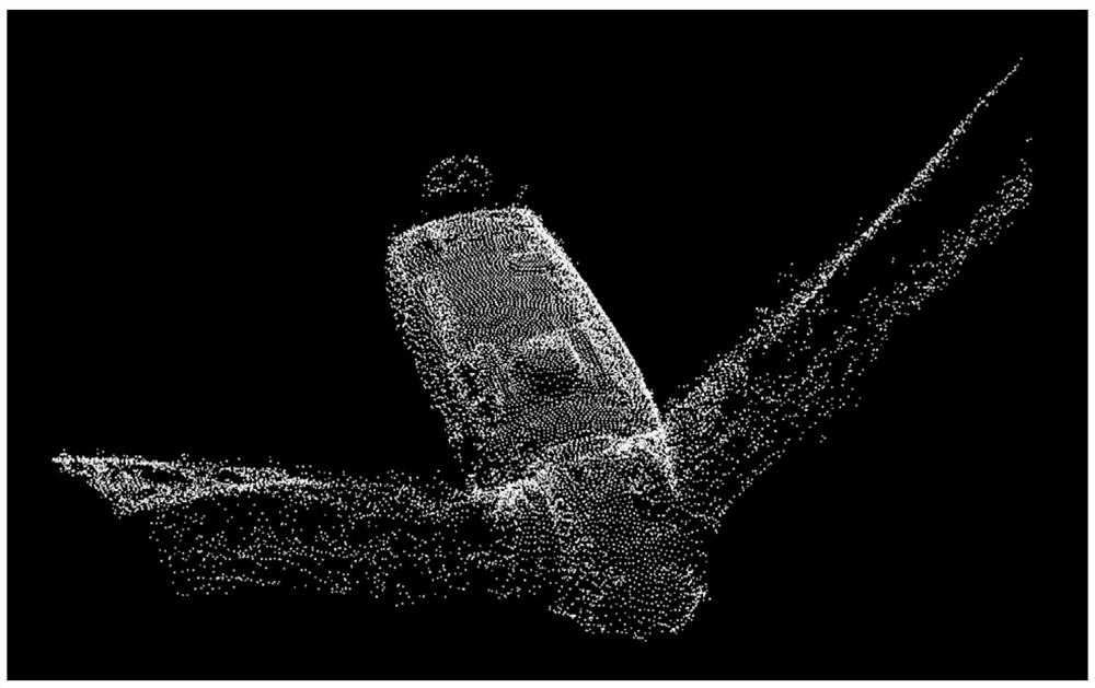
[0058] Step S1. First, according to the pre-input geographic coordinates of the wind turbine and the absolute altitude of the nacelle, a route for photogrammetry of the nacelle is generated, and the UAV collects images according to the photogrammetry route; secondly, the UAV’s airborne The calculation unit performs aerial triangulation calculations on the collected images according to known and mature methods, and produces point cloud results;
[0059] Among them, the route of photogrammetry is based on the geographic coordinates of the yaw rotation center point of the wind turbine and the absolute altitude of the nacelle as the center of collection, and generates a circle acquisition route centered on this point and the photogrammetry lens always points to this point Or reciprocating collection routes;
[0060] I...
Embodiment 2
[0069] A method for determining the yaw angle of a wind rotor by using an unmanned aerial vehicle, comprising the following steps:
[0070] Step S1. First, according to the pre-input geographic coordinates of the wind turbine and the absolute altitude of the nacelle, a route for photogrammetry of the nacelle is generated, and the UAV collects images according to the photogrammetry route; secondly, the UAV’s airborne The calculation unit performs aerial triangulation calculations on the collected images according to known and mature methods, and produces point cloud results;
[0071] Step S2, slice the point cloud according to the elevation of the center point of the cabin, and process the point cloud into multiple independent slices of continuous elevation ranges;
[0072] Step S3, flattening each slice, such as Figure 9 As shown, the points within ±0.25m of the point cloud can be sliced and flattened according to the elevation of the center point of the engine room. In th...
Embodiment 3
[0076] A method for determining the yaw angle of a wind rotor by using an unmanned aerial vehicle, comprising the following steps:
[0077] Step S1. First, according to the pre-input geographic coordinates of the wind turbine and the absolute altitude of the nacelle, a route for photogrammetry of the nacelle is generated, and the UAV collects images according to the photogrammetry route; secondly, the UAV’s airborne The calculation unit performs aerial triangulation calculations on the collected images according to known and mature methods, and produces point cloud results;
[0078] Step S2, slice the point cloud according to the elevation of the center point of the cabin, and process the point cloud into multiple independent slices of continuous elevation ranges;
[0079] Step S3, flattening each slice, such as Figure 9 As shown, the points within ±0.25m of the point cloud can be sliced and flattened according to the elevation of the center point of the engine room. In th...
PUM
 Abstract
Description
Claims
Application Information
 - R&D
- Intellectual Property
- Life Sciences
- Materials
- Tech Scout
- Unparalleled Data Quality
- Higher Quality Content
- 60% Fewer Hallucinations
Browse by: Latest US Patents, China's latest patents, Technical Efficacy Thesaurus, Application Domain, Technology Topic, Popular Technical Reports.
© 2025 PatSnap. All rights reserved.Legal|Privacy policy|Modern Slavery Act Transparency Statement|Sitemap|About US| Contact US: help@patsnap.com


