
Lubricating structure for bevel gear bearing

A lubricating structure and bevel gear technology, which is applied in gear lubrication/cooling, bearings, roller bearings, etc., can solve problems such as poor lubrication effect of bevel gear bearings

Pending Publication Date: 2021-07-30
ZHEJIANG ZHAOFENG MECHANICAL & ELECTRONICS CO LTD
View PDF10 Cites 0 Cited by
  • Summary
  • Abstract
  • Description
  • Claims
  • Application Information

AI Technical Summary

Problems solved by technology

[0004] The present invention aims at the disadvantage of poor lubricating effect of bevel gear bearings in the prior art, and provides a lubricating structure for bevel gear bearings

Method used


Image

  • Lubricating structure for bevel gear bearing
  • Lubricating structure for bevel gear bearing
  • Lubricating structure for bevel gear bearing

Examples


Embodiment 1

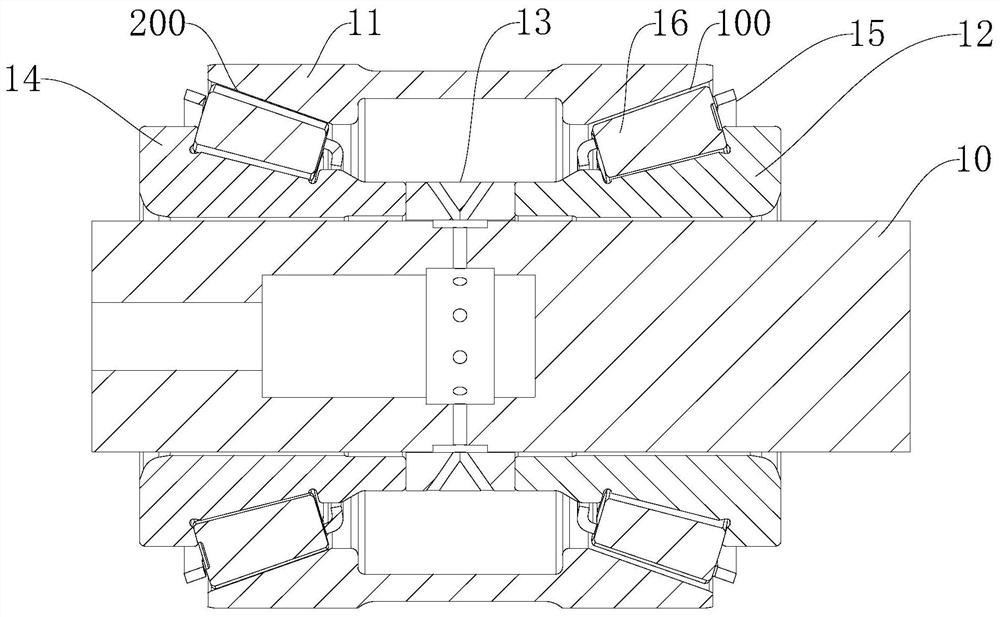
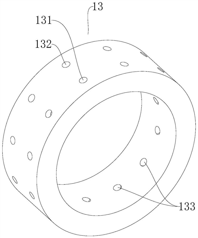
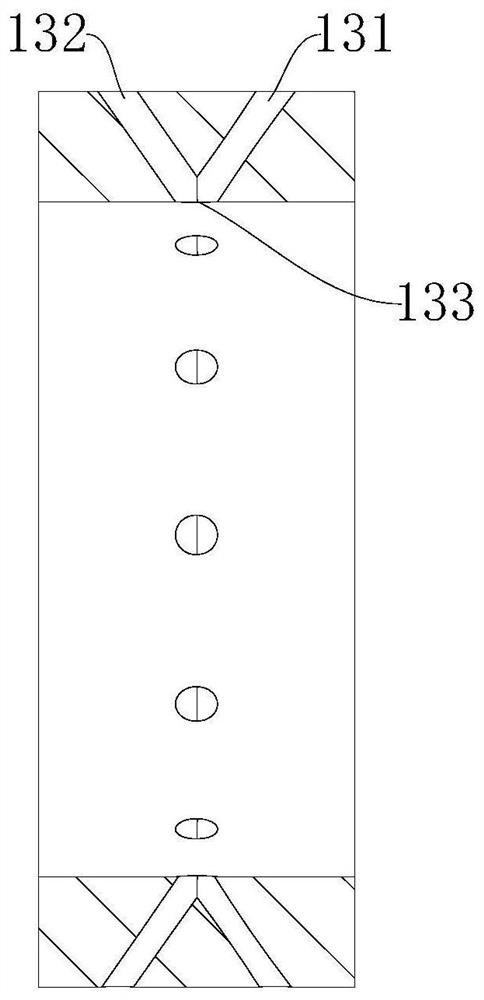
[0037] A lubricating structure for bevel gear bearings, comprising a bevel gear shaft 10, bearings are installed on the bevel gear shaft 10, the bearings include a bearing outer ring 11, a front bearing inner ring 12 and a rear bearing inner ring 14, the bearings include a front bearing and Rear bearing, front bearing and rear bearing are provided with a bearing outer ring 11, form front raceway 100 between bearing outer ring 11 and front bearing inner ring 12, and front raceway 100 is ring tapered raceway. A rear raceway 200 is formed between the bearing outer ring 11 and the rear bearing inner ring 14, and the rear raceway 200 is also a ring-tapered raceway. On the bevel gear shaft 10, an oil throwing ring 13 is installed, and the oil throwing ring 13 is located between the front bearing inner ring 12 and the rear bearing inner ring 14. 14 contact connections, the outer circumference diameter of the oil throwing ring 13 is equal to the inner end outer circumference diameter ...

Embodiment 2

[0047] Embodiment 2 has basically the same features as Embodiment 1, except that the diameter of the front oil pump hole 131 and the rear oil pump hole 132 are both 0.75 mm. The diameter of the oil throwing hole 133 is 2.75 mm.

Embodiment 3

[0049] Embodiment 3 has basically the same features as Embodiment 1, except that the diameter of the front oil pump hole 131 and the rear oil pump hole 132 are both 1 mm. The diameter of the oil throwing hole 133 is 5mm.


PUM


Abstract

The invention relates to a bearing lubricating structure, and discloses a lubricating structure for a bevel gear bearing, which comprises a bevel gear shaft; the bevel gear shaft is provided with a bearing; the bearing comprises a bearing outer ring, a front bearing inner ring and a rear bearing inner ring; a front raceway is formed between the bearing outer ring and the front bearing inner ring, and a rear raceway is formed between the bearing outer ring and the rear bearing inner ring; an oil slinger is installed on the bevel gear shaft and arranged between the front bearing inner ring and the rear bearing inner ring; a negative suction hole and an oil collecting groove communicated with the negative suction hole are arranged in the bevel gear shaft; a plurality of oil conveying holes are arranged on the circumferential side wall of the oil collecting groove; a front oil pumping hole and a rear oil pumping hole which are both communicated with the oil conveying holes are arranged on the oil slinger; and the front oil pumping hole faces the front raceway, and the rear oil pumping hole faces the rear raceway. Lubricating oil in a gear box is led into a bearing cavity through the negative suction hole and a negative suction gear shaft to achieve lubrication, the bearing outer ring and a shell runner are simplified, and meanwhile the problem of poor lubrication caused by the fact that a front bearing is located at a high position is avoided.

Description

technical field [0001] The invention relates to a bearing lubricating structure, in particular to a lubricating structure for bevel gear bearings. Background technique [0002] The main bevel gear bearing of the main reducer adopts splash lubrication, that is, the gear box is used as an oil tank, and an oil collecting groove, an oil inlet hole and an oil return hole are arranged on the reducer shell, and the lubricating oil is thrown in through the oil passage through the rotation of the main bevel gear. Lubrication is carried out in the bearing cavity, and the lubricating oil flows from the small end to the large end under the action of the pump oil generated when the tapered roller rotates, and flows back to the gearbox through the oil return hole to realize the lubrication of the bearing and the circulation of the lubricating oil. [0003] However, the front bearing of the main bevel gear is far away from the oil surface and the gear, and the rear bearing is separated, so...

Claims


Application Information

Patent Timeline
Patent Type & Authority Applications(China)
IPC IPC(8): F16H57/04F16C33/66F16C19/38F16C33/58
CPCF16H57/0428F16H57/0471F16C33/6666F16C19/385F16C33/581
Inventor 马春红孔辰寰雷良育康乃正方志启
Owner ZHEJIANG ZHAOFENG MECHANICAL & ELECTRONICS CO LTD
Learn More