
Automatic adhesive dispensing and pushing mechanism for electronic element

A technology for electronic components and automatic dispensing, which is applied to devices and coatings that apply liquid to the surface. It can solve the problems of high difficulty and small size of common mode inductance, and achieve high work efficiency, high production efficiency, and saving positioning. The effect of dispensing time

Active Publication Date: 2021-08-03
DONGGUAN TB ELECTRONICS TECH CO LTD
View PDF12 Cites 1 Cited by
  • Summary
  • Abstract
  • Description
  • Claims
  • Application Information

AI Technical Summary

Problems solved by technology

[0003] In the manufacturing process of common mode inductors, copper wires need to be wound on the main body to form electronic components, and then the shell plate is glued to the electronic components to realize the manufacture of electronic components; the existing manufacturing process of common mode inductors Among them, manual semi-automatic glue dispensing is generally used. Because some common mode inductors are very small in size, it is extremely difficult in manual manufacturing and production.

Method used


Image

  • Automatic adhesive dispensing and pushing mechanism for electronic element
  • Automatic adhesive dispensing and pushing mechanism for electronic element
  • Automatic adhesive dispensing and pushing mechanism for electronic element

Examples


Embodiment Construction

[0030] In order to facilitate the understanding of the present invention, the present invention will be described more fully below with reference to the associated drawings. Preferred embodiments of the invention are shown in the accompanying drawings. However, the present invention can be embodied in many different forms and is not limited to the embodiments described herein. On the contrary, these embodiments are provided to make the understanding of the disclosure of the present invention more thorough and comprehensive.

[0031] It should be noted that when an element is referred to as being “fixed” to another element, it can be directly on the other element or there can also be an intervening element. When an element is referred to as being "connected to" another element, it can be directly connected to the other element or intervening elements may also be present.

[0032]Unless otherwise defined, all technical and scientific terms used herein have the same meaning as ...


PUM


Abstract

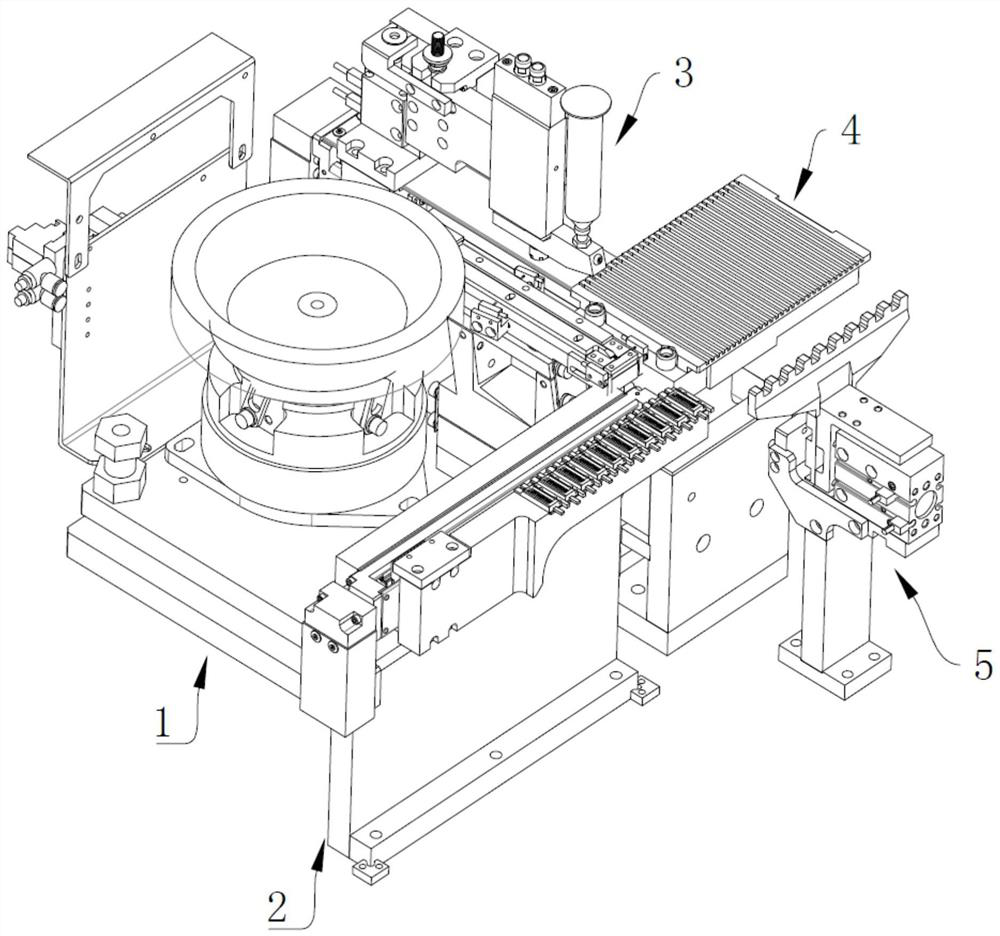
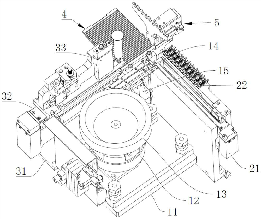
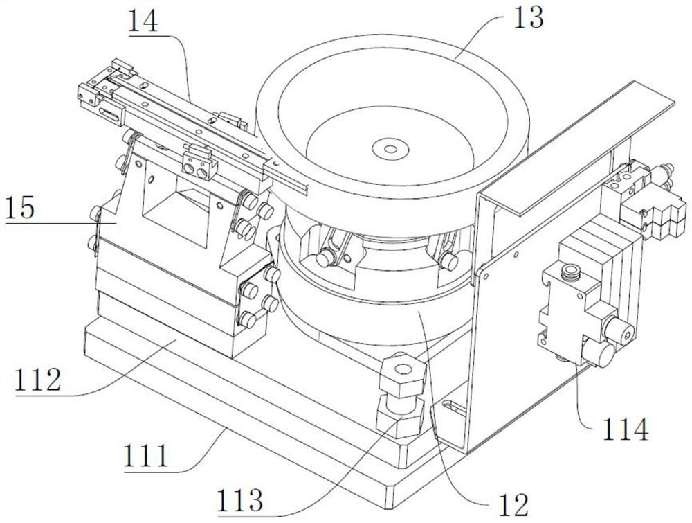
The invention relates to the technical field of electronic element adhesive dispensing, in particular to an automatic adhesive dispensing and pushing mechanism for an electronic element. The automatic adhesive dispensing and pushing mechanism for the electronic element comprises a material supplying device used for supplying the electronic element, a feeding device connected to the material supplying device and used for receiving the electronic elements supplied by the material supplying device, an adhesive dispensing device arranged on one side of the feeding device and used for dispensing adhesive on the electronic elements on the feeding device, a material tray device arranged on one side of the feeding device and used for receiving the electronic elements with the dispensed adhesive on the feeding device, and a pushing device arranged on one side of the material tray device and used for pushing the electronic elements on the feeding device into the material tray device. According to the automatic adhesive dispensing and pushing mechanism for the electronic element, adhesive dispensing is conducted in the linear conveying process after feeding, the electronic elements reach the front end of the material tray after adhesive dispensing, then the electronic elements are pushed into the material tray through the pushing device, full-automatic feeding, conveying, adhesive dispensing, material pushing and tray charging are achieved, the overall automation degree is high, manpower is saved, and the production efficiency is high.

Description

technical field [0001] The invention relates to the technical field of dispensing electronic components, in particular to an automatic dispensing and pushing mechanism for electronic components. Background technique [0002] As the application of electronic products becomes more and more extensive, the production of various components in electronic products is becoming more and more important, and inductors, as one of the three major components, are becoming more and more important. Among them, common-mode inductors are often used in switching power supplies of computers to filter common-mode electromagnetic interference signals. In the board design, the common mode inductor also plays the role of EMI filter, which is used to suppress the electromagnetic wave generated by the high-speed signal line from radiating outward. [0003] In the manufacturing process of common mode inductors, copper wires need to be wound on the main body to form electronic components, and then the...

Claims


Application Information

Patent Timeline
IPC IPC(8): B05C13/02B05C5/02
CPCB05C13/02B05C5/0208
Inventor 温小金黄天碧
Owner DONGGUAN TB ELECTRONICS TECH CO LTD
Learn More