Unlock instant, AI-driven research and patent intelligence for your innovation.

Optical unit with shake correction function

A technology of jitter correction and optical unit, applied in optical components, optics, instruments, etc., can solve the problems of not easy to handle multiple balls, complicated structure of support mechanism, etc.

Inactive Publication Date: 2021-08-03
NIDEC CORP
View PDF5 Cites 0 Cited by
  • Summary
  • Abstract
  • Description
  • Claims
  • Application Information

AI Technical Summary

Problems solved by technology

[0005] In a structure in which the support mechanism supporting the movable body has a plurality of balls rolling between the fixed body and the movable body, it may be difficult to handle the plurality of balls when manufacturing the device
In addition, when a ball having a convex spherical surface is supported so as to be able to roll by a movable body having a convex spherical surface, the structure of the support mechanism may become complicated.

Method used


Image

  • Optical unit with shake correction function
  • Optical unit with shake correction function
  • Optical unit with shake correction function

Examples


Embodiment Construction

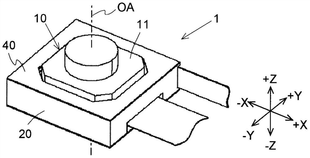
[0021] Hereinafter, exemplary embodiments of the present invention will be described in detail with reference to the drawings. In this manual, the figure 1 The direction parallel to the optical axis OA of the illustrated optical module 11 is called "optical axis direction", and the direction perpendicular to the optical axis OA centered on the optical axis OA is called "radial direction". In addition, in this specification, three axes perpendicular to each other are referred to as an X axis, a Y axis, and a Z axis. Let one side of the X direction along the X axis be the +X direction, and let the other side be the −X direction. One side of the Y direction along the Y axis is referred to as +Y direction, and the other side is referred to as −Y direction. One side of the Z direction along the Z axis is referred to as +Z direction, and the other side is referred to as −Z direction. In addition, the Z direction is a direction parallel to the optical axis direction. The +Z direc...


PUM


Abstract

An optical unit with a shake correction function has a shake correction function for correcting a shake of an optical module. The optical unit with the shake correction function includes: a movable body including the optical module; a fixed body disposed outward of the movable body in a radial direction with respect to an optical axis of the optical module; and a support part disposed between the movable body and the fixed body in the radial direction and structured to support the movable body such that the movable body is swingable relative to the fixed body. The movable body and the support part or the support part and the fixed body have, in a pair, a swing mechanism structured to allow the movable body to swing relative to the fixed body. The swing mechanism includes a protruded spherical portion and a recessed spherical portion that is larger in radius of curvature than the protruded spherical portion.

Description

technical field [0001] The invention relates to an optical unit with shake correction function. Background technique [0002] Conventionally, it is known to provide a mechanism for correcting camera shake by swinging or rotating a movable body having a lens in an optical unit mounted on a mobile terminal or a movable body (for example, refer to Patent Document 1). By providing such a mechanism, it is possible to suppress confusion of captured images when the mobile terminal or the mobile body moves. [0003] A conventional imaging device has a support unit that supports a movable member that supports at least a part of the imaging unit that obtains an image of a subject so as to be capable of swinging at a center point of oscillation on an optical axis of an optical system relative to a fixed member. The center swings the ball. In this imaging device, there are provided: a supported surface, which is provided on the movable member, and is composed of a part of a spherical ...

Claims


Application Information

Patent Timeline
Patent Type & Authority Applications(China)
IPC IPC(8): G03B5/00G03B30/00
CPCG03B5/00G02B27/646
Inventor 田中元纪江川智浩岩濑敬之佐斋一宏新井努南泽伸司须江猛
Owner NIDEC CORP