Automatic cleaning protection device for lens after use of projector
A technology for automatic cleaning and protection devices, which is applied to cleaning methods using tools, projection devices, instruments, etc., can solve problems such as troublesome operation, affect the clarity of the picture, damage the lens, etc., and achieve the effect of convenient cleaning.
- Summary
- Abstract
- Description
- Claims
- Application Information
AI Technical Summary
Problems solved by technology
Method used
Image

Examples
Embodiment 1
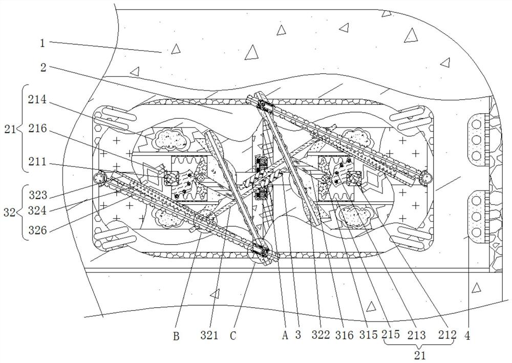
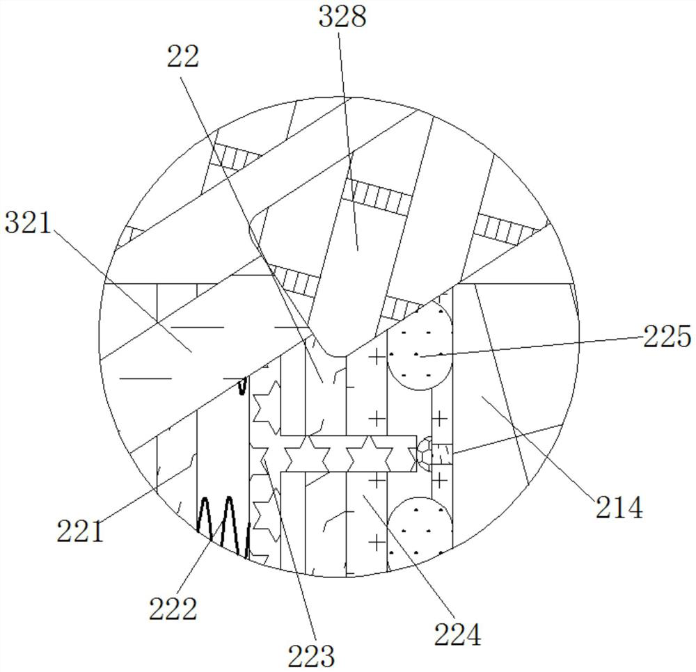
[0030] see Figure 1-2 , an automatic cleaning protection device for the lens after the projector is used, comprising a housing 1, a closing mechanism 2 is movably connected to the inner side of the housing 1, and the closing mechanism 2 includes a translation assembly 21 and a detection assembly 22, and the translation assembly 21 is movably connected to the shell 1 Inside, the translation assembly 21 includes a rotating shaft 1 211, the rotating shaft 211 is movably connected inside the housing 1, the rotating block 212 is fixedly connected to the outside of the rotating shaft 211, the short rod 213 is fixedly connected to the outside of the rotating block 212, and the flat plate 214 is movably connected to the The inner side of the housing 1, the rack 215 is fixedly connected to the outer side of the flat plate 214; the outer side of the rotating shaft 211 is fixedly connected to the motor 1 216, and the motor 1 216 is fixedly connected to the inner side of the housing 1, an...
Embodiment 2
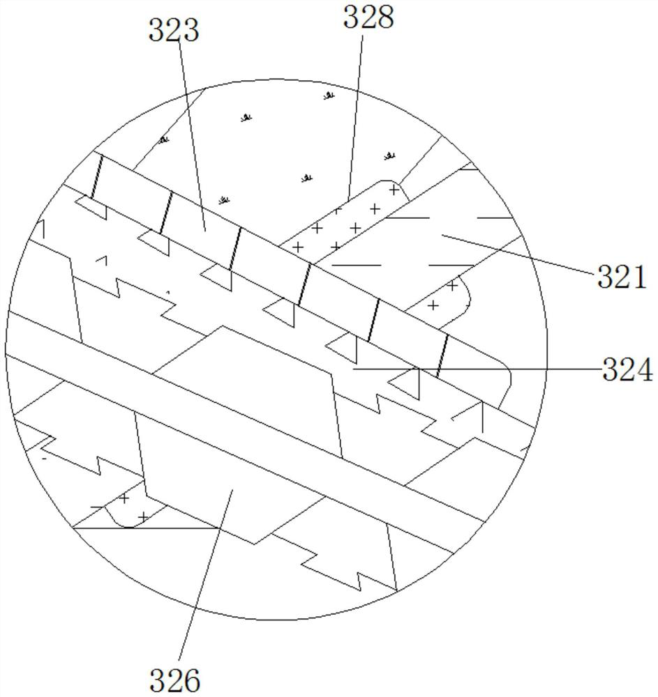
[0033] see figure 1 , 3, 4. An automatic cleaning protection device for the lens after the projector is used, including a housing 1, the inner side of the housing 1 is movably connected with a closing mechanism 2, and the closing mechanism 2 includes a translation assembly 21 for closing the flat plate 214, and a control transmission assembly 31 for movement The detection assembly 22, the translation assembly 21 is movably connected to the inner side of the housing 1, the detection assembly 22 is movably connected to the inside of the translation assembly 21, and the outside of the closing mechanism 2 is movably connected to a cleaning mechanism 3, and the cleaning mechanism 3 includes a transmission assembly 31, a cleaning assembly 32. The transmission assembly 31 is movably connected to the outside of the translation assembly 21. The transmission assembly 31 includes a rotating shaft 2 311. The rotating shaft 311 is movably connected to the inside of the plate 214. The eccen...
Embodiment 3
[0036] see Figure 1-5 , an automatic cleaning protection device for the lens after the projector is used, comprising a housing 1, a closing mechanism 2 is movably connected to the inner side of the housing 1, and the closing mechanism 2 includes a translation assembly 21 and a detection assembly 22, and the translation assembly 21 is movably connected to the shell 1 Inside, the translation assembly 21 includes a rotating shaft 1 211, the rotating shaft 211 is movably connected inside the housing 1, the rotating block 212 is fixedly connected to the outside of the rotating shaft 211, the short rod 213 is fixedly connected to the outside of the rotating block 212, and the flat plate 214 is movably connected to the The inner side of the housing 1, the rack 215 is fixedly connected to the outer side of the flat plate 214; the outer side of the rotating shaft 211 is fixedly connected to the motor 1 216, and the motor 1 216 is fixedly connected to the inner side of the housing 1, an...
PUM
 Abstract
Description
Claims
Application Information
 - R&D
- Intellectual Property
- Life Sciences
- Materials
- Tech Scout
- Unparalleled Data Quality
- Higher Quality Content
- 60% Fewer Hallucinations
Browse by: Latest US Patents, China's latest patents, Technical Efficacy Thesaurus, Application Domain, Technology Topic, Popular Technical Reports.
© 2025 PatSnap. All rights reserved.Legal|Privacy policy|Modern Slavery Act Transparency Statement|Sitemap|About US| Contact US: help@patsnap.com