

Surgical instrument cleaning device
A cleaning device and surgical instrument technology, applied in the medical field, can solve the problems of low manual cleaning efficiency and achieve the effect of improving the cleaning effect and efficiency
- Summary
- Abstract
- Description
- Claims
- Application Information
AI Technical Summary
Problems solved by technology
Method used
Image

Examples
Embodiment 1
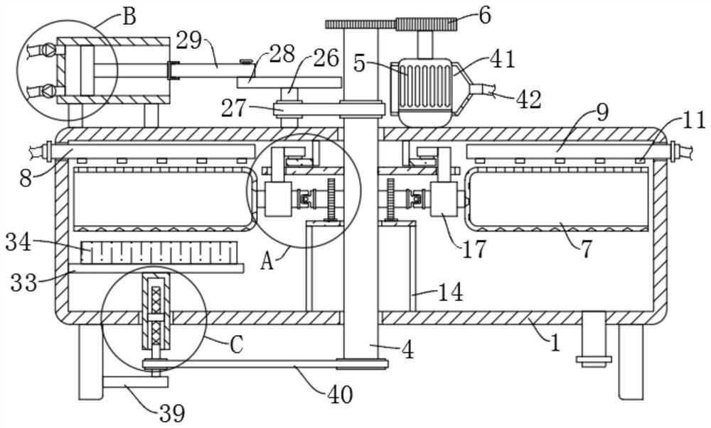
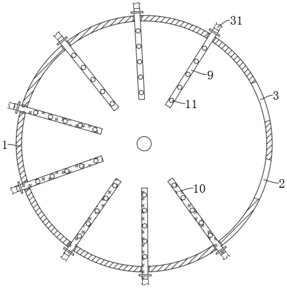
[0032] refer to Figure 1-7 , a surgical instrument cleaning device, comprising a cleaning box 1, the side wall of the cleaning box 1 is provided with an adjacent placement port 2 and a pick-up port 3, a rotating shaft 4 is connected between the upper and lower inner walls of the cleaning box 1, and the cleaning box 1 A motor 5 is fixedly installed on the upper end of the motor 5, and the output end of the motor 5 and the rotating shaft 4 are engaged and connected by two first gears 6. The cleaning box 1 is provided with a plurality of circumferentially distributed cylindrical net covers 7, and the inside of the cleaning box 1 The top is fixed with a plurality of water spray pipes 10 and air spray pipes 9, and the lower ends of the plurality of air spray pipes 9 and water spray pipes 10 are provided with nozzles 11, and the plurality of cylindrical net covers 7 and the rotating shaft 4 are connected by a rotation mechanism A plurality of jet pipes 9 are connected with the rota...
Embodiment 2
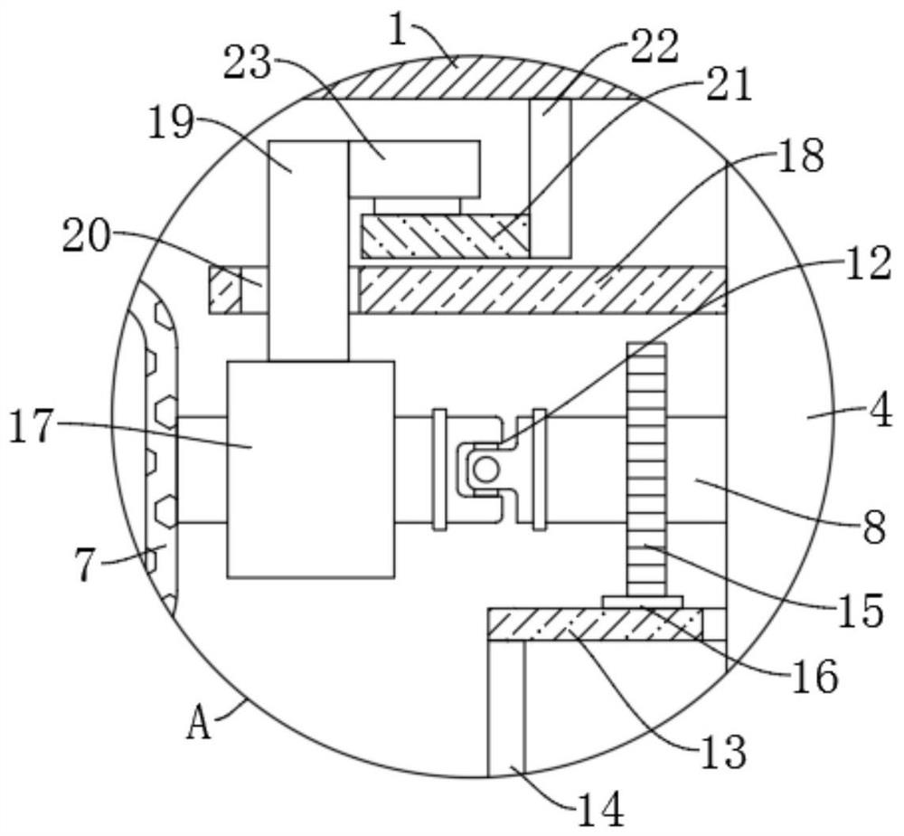
[0034] refer to figure 1 and image 3, is basically the same as Embodiment 1, furthermore: the autorotation mechanism includes a rotating rod 8 that is rotatably connected to the outer wall of the rotating shaft 4, the side wall of the cylindrical net cover 7 is fixedly connected to the end of the rotating rod 8, and the middle part of the rotating rod 8 The cardan shaft 12 is fixedly installed, the outer wall of the rotating rod 8 is fixedly connected with the second gear 15, the outer wall of the rotating shaft 4 is provided with a ring 13, and the upper end of the ring 13 is fixedly connected with the ring gear 16 meshing with the second gear 15 , the ring 13 is fixedly connected with the inner wall of the cleaning box 1 through the bracket 14, and the rotating rod 8 is connected with the inner top of the cleaning box 1 through a sliding mechanism. When the rotating shaft 4 drives the cylindrical net cover 7 to rotate, the second gear 15 will Rotating under the action of t...
Embodiment 3
[0036] refer to figure 1 , image 3 as well as Figure 6 , is basically the same as Embodiment 1, furthermore: the sliding mechanism includes a sleeve 17 that is sleeved on the outer wall of the rotating rod 8 during rotation, the outer wall of the rotating shaft 4 is fixedly connected with a first disc 18, and the side wall of the sleeve 17 is fixed. Connected with a vertical rod 19, the upper end of the first disc 18 is provided with a chute 20 cooperating with the vertical rod 19, the inner top of the cleaning box 1 is fixedly connected with an annular plate 21 through a support rod 22, and the upper end of the vertical rod 19 is fixedly connected with a The guide slider 23 that is against the upper end of the annular plate 21, the upper end of the annular plate 21 is provided with an arc surface groove 24, the arc surface groove 24 corresponds to the position of the pick-up port 3, and the rotating shaft 4 drives the cylindrical net cover 7 to rotate in a circle When rea...
PUM
 Abstract
Description
Claims
Application Information