Milling device for metal saw blade machining

A milling device and saw blade technology, applied in metal processing equipment, metal processing machinery parts, metal sawing equipment, etc., can solve the problems of reducing milling precision, difficult to clean milling cutter and saw blade debris, and affecting the cleanliness of coolant, etc., to achieve The effect of improving milling precision and improving cleanliness

Pending Publication Date: 2021-08-06
江苏天硕合金材料有限公司
View PDF8 Cites 2 Cited by
  • Summary
  • Abstract
  • Description
  • Claims
  • Application Information

AI Technical Summary

Problems solved by technology

[0004] The invention provides a milling device for metal saw blade processing, which solves the problem that it is difficult to clean all debris on the milling cutter and saw blade when the coolant is sprayed on the milling cutter and the saw blade, and the debris remains in the gap of the milling cutter , reduce the precision of milling, the falling direction of the coolant is consistent with the falling direction of the debris generated by milling, after the coolant and debris are collected, the cleanliness of the coolant will be affected, and a large amount of coolant will be used during the milling process. It is necessary to frequently add coolant to the coolant tank, and the operation is too cumbersome

Method used


Image

  • Milling device for metal saw blade machining
  • Milling device for metal saw blade machining
  • Milling device for metal saw blade machining

Examples


Embodiment Construction

[0025] The following will clearly and completely describe the technical solutions in the embodiments of the present invention with reference to the accompanying drawings in the embodiments of the present invention. Obviously, the described embodiments are only some, not all, embodiments of the present invention. Based on the embodiments of the present invention, all other embodiments obtained by persons of ordinary skill in the art without making creative efforts belong to the protection scope of the present invention.

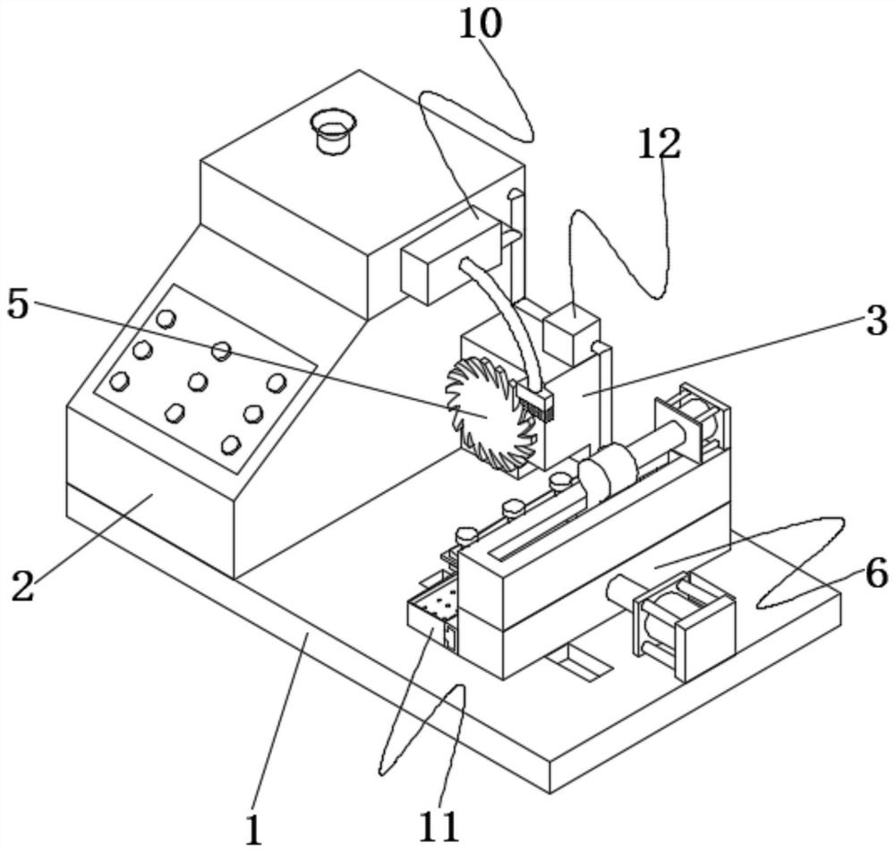
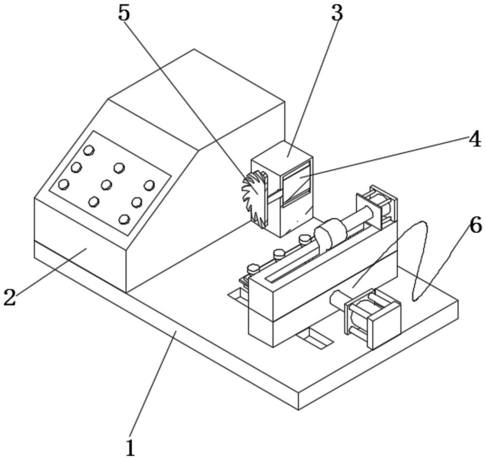
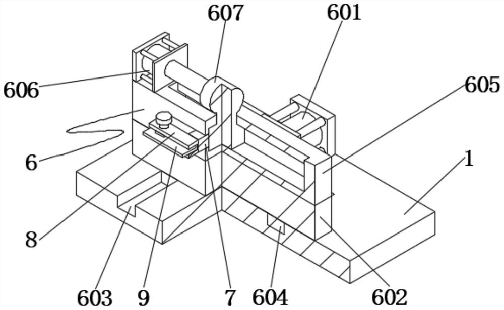
[0026] see Figure 1-6 , the present invention provides a technical solution: a milling device for processing metal saw blades, including a console 1, a console 2 is fixedly connected to one end of the top of the console 1, and one side of the console 2 is fixedly connected to a cabinet 3, the cabinet 3 A motor 4 is installed inside, and the output end of the motor 4 is fixedly connected with a milling cutter 5. The upper part of the console 1 and the end far ...


PUM


Abstract

The invention discloses a milling device for metal saw blade processing. The milling device comprises an operation table, wherein a control table is fixedly connected to one end of the upper part of the operation table, a case is fixedly connected to one side of the control table, a motor is mounted in the case, a milling cutter is connected to a fixing nail at the output end of the motor, a feeding mechanism is arranged at one end of the upper part of the operation table far away from the control table, the feeding mechanism is fixedly connected with a connecting arm, the connecting arm is fixedly connected with a clamp, a saw blade is fixedly connected into the clamp, the upper portion of the control table is fixedly connected with a cooling mechanism, the end, away from the control table, of the cooling mechanism is located above the milling cutter, a collecting mechanism is arranged on one side of the feeding mechanism, and the cooling mechanism and the collecting mechanism are connected through a circulating mechanism. The invention relates to the technical field of saw blade machining. According to the milling device for metal saw blade machining, chippings in gaps of a milling cutter are brushed through the bristles on a connector, so that the chippings on the milling cutter are cleaned more cleanly, and the milling precision of the milling cutter is improved.

Description

technical field [0001] The invention relates to the technical field of saw blade processing, in particular to a milling device for metal saw blade processing. Background technique [0002] Saw blades are steel strips with toothed edges, and the toothed edges are the main components of saw blades. Saw blades are usually divided into bimetallic saw blades, carbonized sand saw blades, high-speed steel saw blades and carbon steel saw blades. At present, milling machines are usually used for saw blades. Edge processing. [0003] When the milling machine is processing the saw blade, it is necessary to use coolant to cool the milling cutter and the saw blade to prevent the temperature from being too high, and when the coolant is sprayed on the milling cutter, it can also wash away the debris on the milling cutter, but it is difficult to clean Clean all the debris on the milling cutter. The debris remaining in the gap of the milling cutter will reduce the milling accuracy to a cert...

Claims


Application Information

Patent Timeline
Patent Type & Authority Applications(China)
IPC IPC(8): B23D65/04B23Q11/00B23Q11/10B23C3/00
CPCB23D65/04B23Q11/0075B23Q11/1069B23Q11/10B23C3/00
Inventor 王庆顺
Owner 江苏天硕合金材料有限公司
Why Eureka
Try Eureka