Auxiliary mechanism facilitating butt joint of building steel pipes

An auxiliary mechanism and steel pipe technology, which is applied in welding/cutting auxiliary equipment, auxiliary devices, auxiliary welding equipment, etc., can solve the problems of inconvenient welding, low cooling efficiency, time-consuming and laborious fixed welding, etc. The effect of welding precision

Pending Publication Date: 2021-08-06
牟丹
View PDF6 Cites 5 Cited by
  • Summary
  • Abstract
  • Description
  • Claims
  • Application Information

AI Technical Summary

Problems solved by technology

[0004] Aiming at the deficiencies of the prior art, the present invention provides an auxiliary mechanism for butt jointing of construction steel pipes, which solves the problems of time-consuming and laborious fixing welding, inconvenient welding and low cooling efficiency

Method used


Image

  • Auxiliary mechanism facilitating butt joint of building steel pipes
  • Auxiliary mechanism facilitating butt joint of building steel pipes
  • Auxiliary mechanism facilitating butt joint of building steel pipes

Examples


Embodiment 1

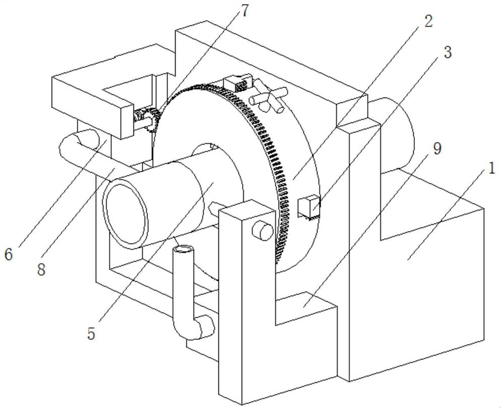
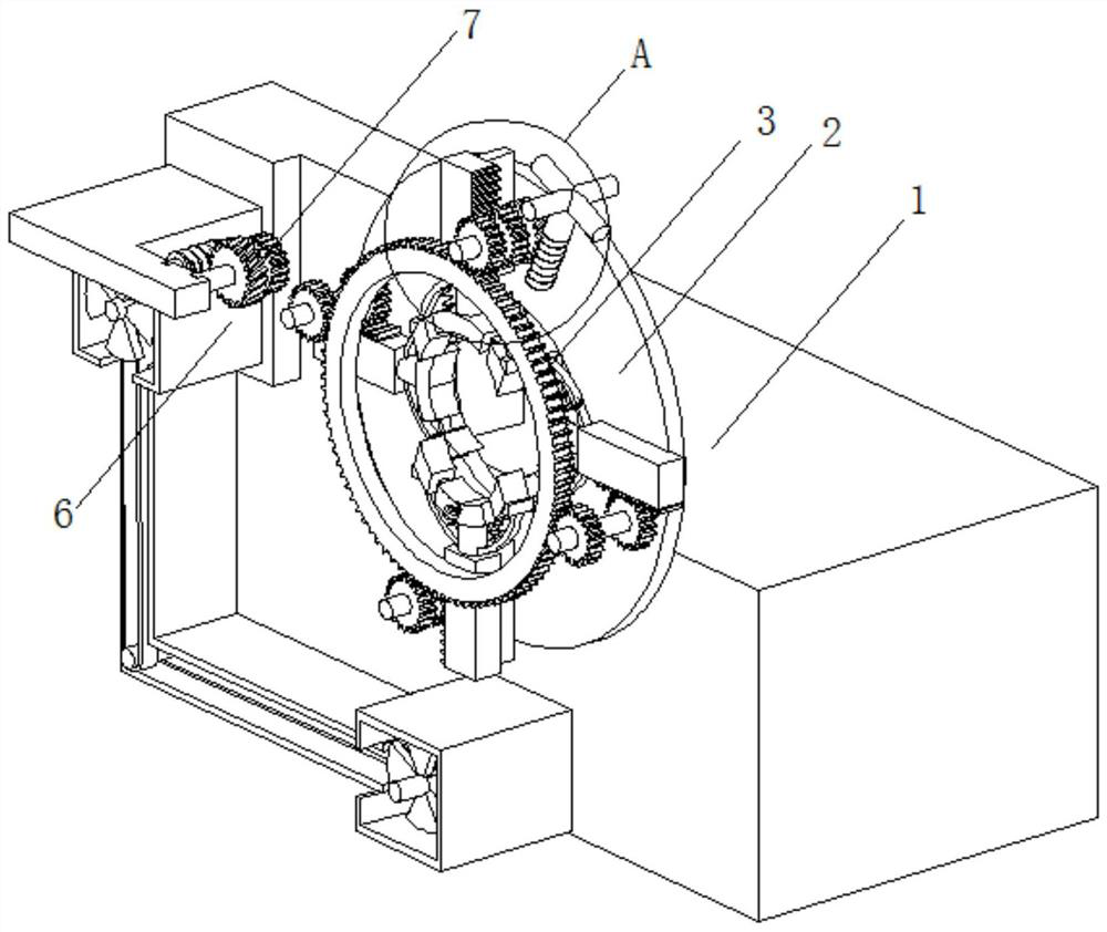
[0031] A aid for aid for building steel pipe docking, such as Figure 1 - Figure 5 As shown, including the pair of receivers, the internal rotation of the pair of recesses 1, and the inside of the rotary seat disk 2 is provided with a fixing mechanism 3, and the surface of the fixing mechanism 3 is provided with a steel pipe body 5, a front portion of the receiving station 1. The bolt is fixedly connected to the protective case 6, and the inner portion of the protective case 6 is provided with a rotating mechanism 7, and the front portion of the protective case 6 is in communication with a blower tube 8, and the front portion of the front portion of the guard box 6 is fixedly connected to the welding machine. Block 9.

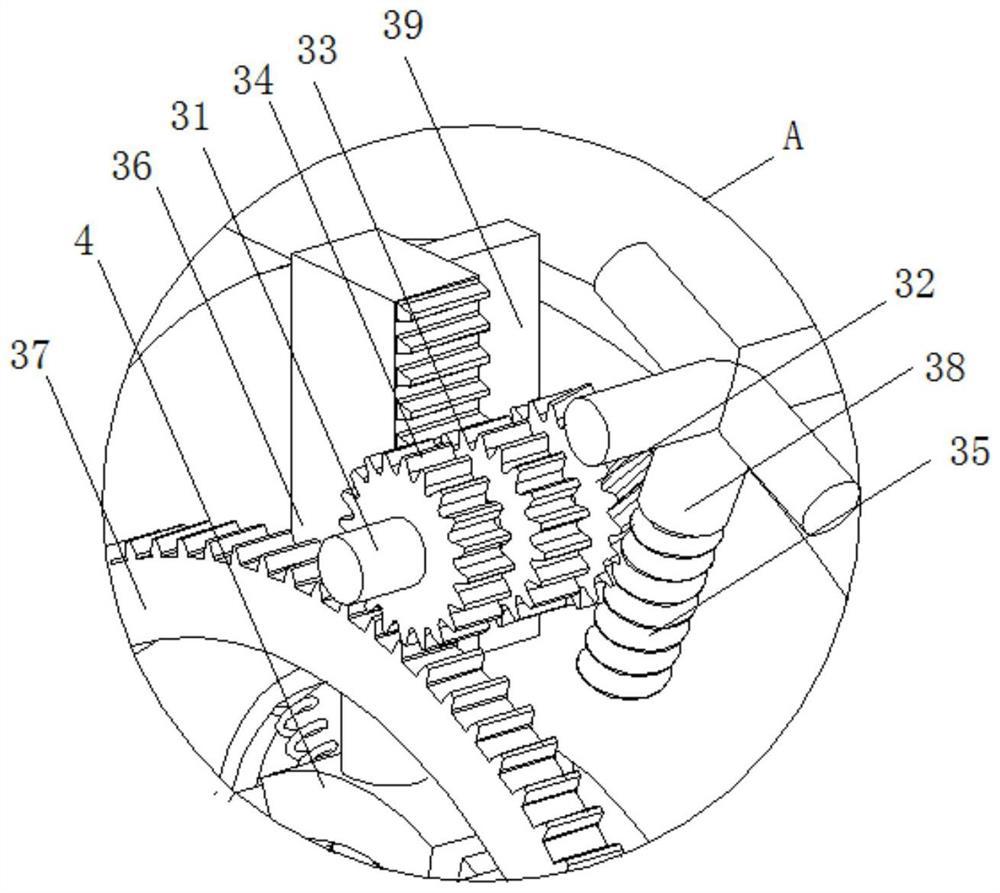
[0032] In the present embodiment, the fixing mechanism 3 includes a conversion post 31, both ends of the column 31, and the inner wall of the rotary seat disc 2, and the surface of the column 31 are welded to have a movable worm wheel 32, the meshing gear 33, and th...

Embodiment 2

[0043] like Figure 6-7 As shown, in the basis of the first embodiment, in the present embodiment, the rotating mechanism 7 includes a motor 71 and a secondary roller 74, and the surface of the motor 71 is fixedly connected to the surface of the panel 1, the output shaft card of the motor 71. In touch with the active roller 72, the front end of the active roller 72 is welded, and the surface welding of the secondary pass roller 74 is welded, and the interior of the interior of the interior of the discharge wheel 75 is engaged with the interior welding of the interior welding of the interior of the discharge wheel 76. The connecting shaft 77, the surface welding of the connecting shaft 77 has a rotating gear 78.

[0044] By providing the rotating mechanism 7, the interaction between the various structures between the rotation mechanism 7 is used to achieve the effect of rotating the welding while the fan 73 is reached, and the steel tube body 5 is rotated in the restriction of the s...


PUM


Abstract

The invention relates to the technical field of steel pipe butt joint, and discloses an auxiliary mechanism facilitating butt joint of building steel pipes. The auxiliary mechanism comprises a butt joint table, the interior of the butt joint table is rotatably connected with a rotating seat disc, the interior of the rotating seat disc is provided with a fixing mechanism, and the surface of the fixing mechanism is provided with steel pipe bodies; and the front portion of the butt joint table is fixedly connected with a protection box through bolts, a rotating mechanism is arranged in the protection box, and the front portion of the protection box communicates with an air blowing pipe. According to the auxiliary mechanism facilitating butt joint of the building steel pipes, the effect of synchronously clamping and fixing the steel pipe bodies with different sizes in four directions is achieved through mutual operation of all structures in the fixing mechanism and the rotating mechanism, so that time and labor are saved, the effect that the steel pipe bodies are rotationally welded under the limitation of the inner structure of the rotating seat disc while air cooling is conducted is achieved, the problem that traditional manual surrounding welding is inconvenient is further avoided, and therefore the effect of assisting butt joint of the steel pipes is achieved.

Description

Technical field [0001] The present invention relates to the field of steel pipe docking techniques, and in particular a auxiliary mechanism that facilitates construction steel pipe docking. Background technique [0002] Steel pipe docking in construction project is a common construction process. During the need for multiple steel pipes, the steel pipe is used to facilitate the installation of the plurality of steel pipes, and the conventional tube welding docking process is in pair A limit panel is provided on the tube wall on one side of the interface, and the other side of the steel tube is lifted, and then the tube is welded to the seam. [0003] Two fixed steel pipes need two steel pipes to be operated during welding, but due to the error in the actual operation, the port corresponding to the two steel pipes is difficult to align, and the human pressing or raising the operation can put two steel pipes. The port is aligned, this operating fee is expensive, and the steel pipe p...

Claims


Application Information

Patent Timeline
Patent Type & Authority Applications(China)
IPC IPC(8): B23K37/053B23K37/00
CPCB23K37/053B23K37/003
Inventor 牟丹
Owner 牟丹
Why Eureka
Try Eureka