
Bar fixing mechanism

A technology for fixing mechanisms and bars, applied in the direction of clamping, positioning devices, metal processing machinery parts, etc., can solve the problems of difficult coordination of moving parts, complicated mechanisms, space occupation, etc., and achieve the effect of simple mechanism and simple moving structure

Pending Publication Date: 2021-08-06
深圳宏友金钻石工具有限公司
View PDF0 Cites 0 Cited by
  • Summary
  • Abstract
  • Description
  • Claims
  • Application Information

AI Technical Summary

Problems solved by technology

[0002] At present, the existing bar fixing mechanism usually uses multiple power modules to control the moving parts to fix the workpiece to be processed. However, since multiple power modules jointly control the moving parts, it is difficult to coordinate among the moving parts. Secondly, multiple power modules and common Controlling moving parts is easy to cause complex, bloated and space-consuming mechanism, which is not conducive to miniaturization

Method used


Image

  • Bar fixing mechanism
  • Bar fixing mechanism
  • Bar fixing mechanism

Examples


Embodiment Construction

[0030] The technical solutions in the embodiments of the invention will be clearly and completely described below in conjunction with the drawings in the embodiments of the invention. Obviously, the described embodiments are only part of the embodiments of the invention, not all of them. Based on the embodiments of the invention, all other embodiments obtained by persons of ordinary skill in the art without creative efforts belong to the protection scope of the invention.

[0031] It should be noted that if there is a directional indication (such as up, down, left, right, front, back...) in the embodiment of the invention, the directional indication is only used to explain the position in a certain posture (as shown in the accompanying drawing). ) under the relative positional relationship, movement conditions, etc. between the various components, if the specific posture changes, the directional indication will also change accordingly.

[0032] In addition, if there are descri...


PUM


Abstract

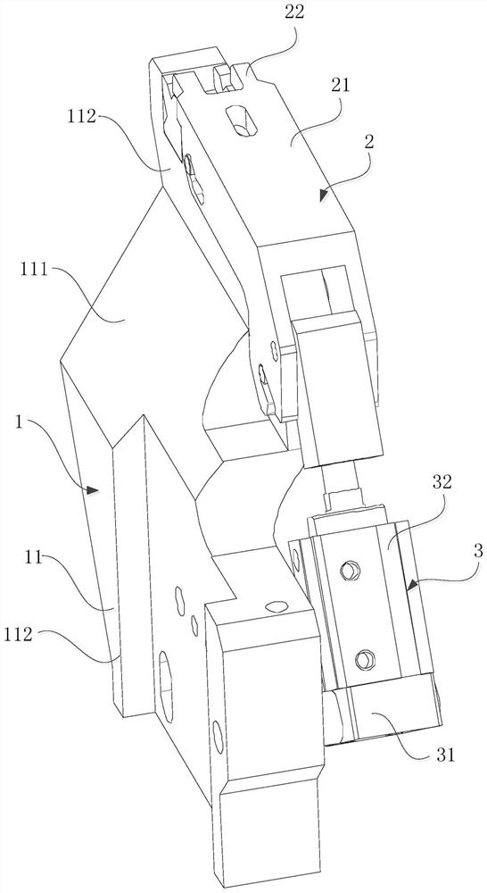
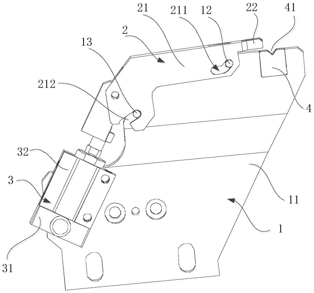
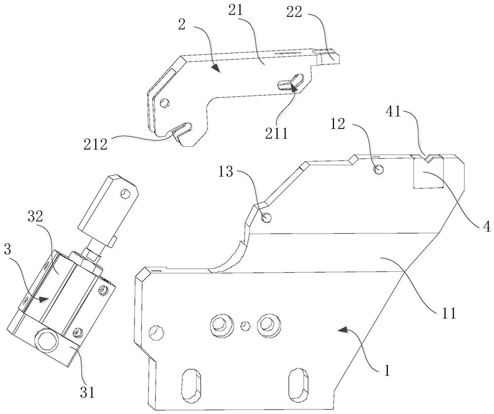
The invention discloses a bar fixing mechanism which comprises a fixing part, a moving part, and a power module. The fixing part comprises a fixing body and first guide protrusions; the first guide protrusions are arranged on the two sides of the fixing body; a mounting groove is formed in the top of the fixing body; a to-be-machined workpiece is arranged in the mounting groove; bending grooves are formed in the two sides of the moving part; the positions of the bending grooves are matched with the positions of the first guide protrusions; the moving part is arranged on the side face, provided with the mounting groove, of the fixed body; the moving part is slidably connected with the fixed body; the first guide protrusions are arranged in the bending grooves; the power module is arranged at the end, away from the mounting groove, of the fixing body; the power module is rotationally connected with the end, away from the mounting groove, of the moving part; the power module drives the moving part to move along a bent groove; and the moving part tightly presses the to-be-machined workpiece arranged in the mounting groove. According to the technical scheme, components of the bar fixing mechanism can be simplified, and movement of the bar mechanism is simplified.

Description

technical field [0001] The invention relates to the field of machining, in particular to a bar fixing mechanism. Background technique [0002] At present, the existing bar fixing mechanism usually uses multiple power modules to control the moving parts to fix the workpiece to be processed. However, since multiple power modules jointly control the moving parts, it is difficult to coordinate among the moving parts. Secondly, multiple power modules and common Controlling moving parts is likely to cause complexity, bulkiness and space occupation of the mechanism, which is not conducive to miniaturization. Contents of the invention [0003] The main purpose of the invention is to propose a bar fixing mechanism, which aims to simplify the pressing mechanism of the equipment, so as to reduce the space occupied by the equipment, so as to achieve the purpose of miniaturization [0004] In order to achieve the above object, the bar fixing mechanism proposed by the invention compris...

Claims


Application Information

Patent Timeline
IPC IPC(8): B23Q3/06B25B11/00
CPCB23Q3/064B25B11/00
Inventor 李敏华
Owner 深圳宏友金钻石工具有限公司
Learn More