
Automatic mechanical clamp used for workpiece overturning and capable of conveniently and rapidly positioning workpiece

A workpiece position and workpiece technology, which is applied in the field of automatic mechanical fixtures and automatic mechanical fixtures for workpiece flipping, can solve the problems of affecting machining accuracy, high labor intensity of workers, and damage to the workpiece surface, so as to reduce the instability of clamping force and practicability Better results with high processing precision

Active Publication Date: 2021-08-06
JIANGSU VOCATIONAL INST OF ARCHITECTURAL TECH
View PDF12 Cites 3 Cited by
  • Summary
  • Abstract
  • Description
  • Claims
  • Application Information

AI Technical Summary

Problems solved by technology

[0002] At present, in the production process of some workpieces, it is often necessary to flip the workpiece as a whole. Manual flipping will cause damage to the surface of the workpiece, and the labor intensity of the workers is high, and the production efficiency is low. Although the existing mechanical fixtures can realize the flipping of the workpiece, due to the flipping process Due to the instability of the fixation, the problem of loosening occurs, which affects the processing accuracy, and every time the mechanical fixture clamps the workpiece, the operator often judges the clamping force artificially, which cannot effectively adapt to the clamping force of different workpieces.

Method used


Image

  • Automatic mechanical clamp used for workpiece overturning and capable of conveniently and rapidly positioning workpiece
  • Automatic mechanical clamp used for workpiece overturning and capable of conveniently and rapidly positioning workpiece
  • Automatic mechanical clamp used for workpiece overturning and capable of conveniently and rapidly positioning workpiece

Examples


Embodiment Construction

[0026] Below in conjunction with accompanying drawing, the present invention will be further described (left, right, front and rear directions and figure 1 The left, right, front and back directions in are the same, just to describe the present invention).

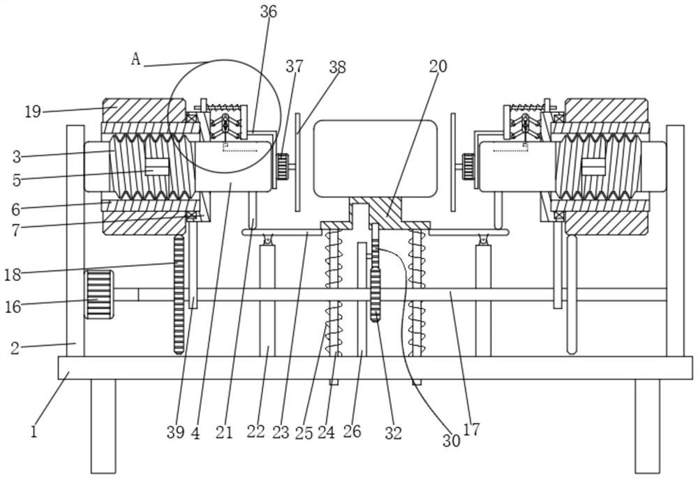
[0027] Such as figure 1 As shown, an automatic mechanical fixture for workpiece turnover that is convenient for quickly locating the position of the workpiece includes a workbench 1, and support plates 2 are fixedly arranged on both ends of the upper surface of the workbench 1, and the opposite sides of the two support plates 2 are arranged There are self-positioning clamping parts;

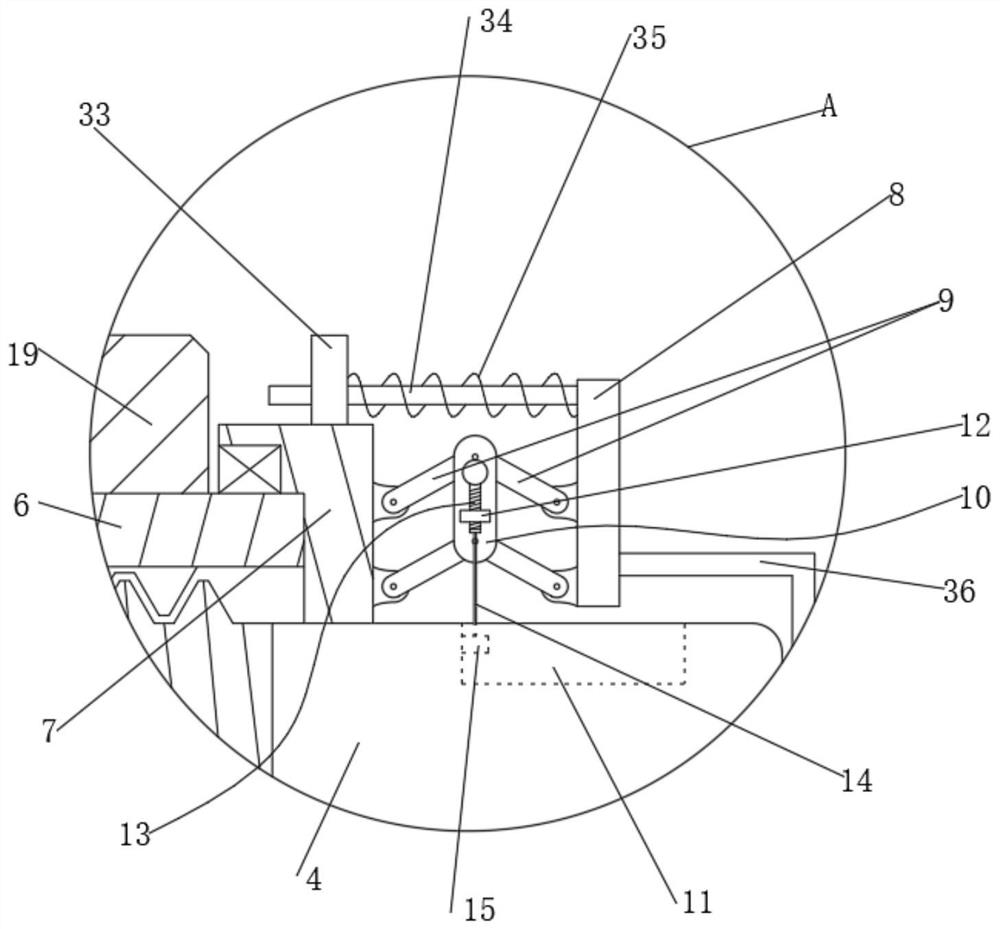
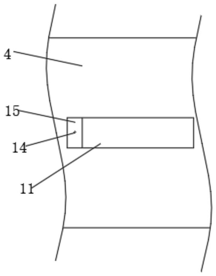
[0028] The self-positioning clamping part includes a first threaded rod 3 fixedly connected to the side of the support plate 2, and also includes a second threaded rod 4. When the first threaded rod 3 and the second threaded rod 4 are spliced ​​into a complete screw rod, A notch 5 is formed on the surface, and the surfaces of the first th...


PUM


Abstract

The invention discloses an automatic mechanical clamp used for workpiece overturning and capable of conveniently and rapidly positioning a workpiece. Self-positioning type clamping parts are arranged on the opposite sides of two supporting plates, the surfaces of a first threaded rod and a second threaded rod are jointly in threaded connection with an inner threaded sleeve, a sleeve is rotationally connected to the surface of the inner threaded sleeve through a fixed shaft, the inner wall of the sleeve is glidingly connected with the surface of the second threaded rod in a sleeving mode, the surface of the sleeve is fixedly connected with a connecting plate through an elastic component, the side surface of the connecting plate is provided with an overturning type extrusion component used for abutting against the workpiece and driving the workpiece to be overturned, each of the opposite sides between the connecting plate and the sleeve is hinged to two connecting rods, the opposite ends of the two connecting rods are jointly hinged to a fixing plate, and the device further comprises a driving part for synchronously driving the two inner threaded sleeves to rotate and move. According to the clamp, the workpiece can be clamped and fixed in a self-positioning mode, meanwhile, the effect of automatically adapting to different workpiece clamping force can be achieved, the machining precision is high, and the phenomenon that the clamping force is unstable due to the fact that the clamping force is manually judged is reduced.

Description

technical field [0001] The invention relates to an automatic mechanical fixture, in particular to an automatic mechanical fixture for workpiece flipping which is convenient for quickly locating the position of the workpiece, and belongs to the technical field of workpiece fixtures. Background technique [0002] At present, in the production process of some workpieces, it is often necessary to flip the workpiece as a whole. Manual flipping will cause damage to the surface of the workpiece, and the labor intensity of the workers is high, and the production efficiency is low. Although the existing mechanical fixtures can realize the flipping of the workpiece, due to the flipping process The problem of loosening due to the instability of the fixation in the middle affects the machining accuracy, and every time the mechanical fixture clamps the workpiece, the operator often judges the clamping force artificially, which cannot effectively adapt to the clamping force of different wo...

Claims


Application Information

Patent Timeline
Patent Type & Authority Applications(China)
IPC IPC(8): B23Q7/00B23Q3/06
CPCB23Q7/00B23Q3/06
Inventor 安淑女戴珊珊程琼肖根先伊登峰康力
Owner JIANGSU VOCATIONAL INST OF ARCHITECTURAL TECH
Learn More