

Automatic polishing device for exported wood furniture
An automatic polishing and furniture technology, applied in the direction of grinding/polishing equipment, metal processing equipment, surface polishing machine tools, etc., can solve the problem of manual loading and unloading of polishing equipment
- Summary
- Abstract
- Description
- Claims
- Application Information
AI Technical Summary
Problems solved by technology
Method used
Image


Examples
Embodiment 1
[0060] An automatic polishing equipment for export wood furniture, such as figure 1 As shown, it includes a first support plate 1, a first support frame 2, a second support plate 3, a second support frame 4, an alignment mechanism 5, a pushing mechanism 6 and a polishing mechanism 7, and the first support plate 1 is uniformly arranged There are a plurality of first support frames 2, and a second support plate 3 is connected between the tops of the plurality of first support frames 2. The front and rear sides of the second support plate 3 are symmetrically provided with four second support frames 4. An alignment mechanism 5 is connected between the inner sides of the support frames 4 , a pushing mechanism 6 is provided on the left side of the rear of the alignment mechanism 5 , and a polishing mechanism 7 is provided on the right side of the alignment mechanism 5 .
[0061] When people need to polish wood furniture, this automatic polishing equipment for export wood furniture c...
Embodiment 2
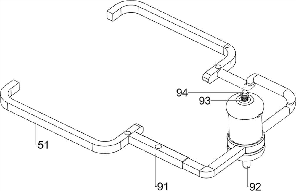
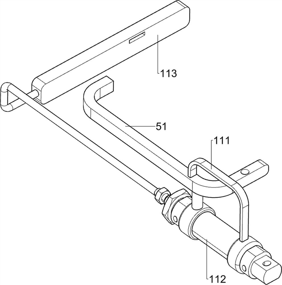
[0063] On the basis of Example 1, such as Figure 2-4As shown, the alignment mechanism 5 includes a third support frame 51, a discharge frame 52, an aligner 53, a first engaging fixed rod 54, a first spring 55 and a first long frame 56, and two second supports on the same side A third support frame 51 is connected between the inner sides of the frame 4, and a discharge frame 52 is connected between the left parts of the two third support frames 51. The right side of the third support frame 51 is slidably provided with an aligner 53, and the aligner 53 and The first spring 55 is connected between the third supporting frame 51, and the first spring 55 is wound on the aligner 53. The first engaging fixing rod 54 is connected between the tops of the two aligners 53, and the right part of the aligner 53 on the rear side is lowered. A first long block frame 56 is provided on the side.
[0064] People put the wooden furniture in the discharge frame 52, then push the pushing mechanis...
Embodiment 3
[0070] On the basis of Example 2, such as Figure 5-8 As shown, it also includes a polishing auxiliary mechanism 8. The polishing auxiliary mechanism 8 includes a plate frame 81, a sixth spring 82 and a fixed round bar assembly 83. The first connecting fixed bar 54 is provided with a fixed round bar assembly 83, and the rear A plate frame 81 is slidingly provided on the third support frame 51 on the side, and a sixth spring 82 is connected between the bottom of the plate frame 81 and the bottom of the third support frame 51 on the rear side. The sixth spring 82 is wound on the plate frame 81 and fixed. Both the round block rod assembly 83 and the fifth support frame 72 cooperate with the block frame 81 .
[0071] The upward movement of the first connecting fixed rod 54 drives the fixed round bar assembly 83 to move upward, thereby driving the plate frame 81 to move upward, the sixth spring 82 is compressed, and when the plate frame 81 moves upward and touches the fifth support...
PUM
 Abstract
Description
Claims
Application Information