Polishing wheel

a polishing wheel and wheel body technology, applied in the field of polishing wheels, can solve the problems of discontinuous surface, rough surface on the surface of the lens, and the polishing method has the disadvantage of requiring a separate lap for each lens prescription,

Inactive Publication Date: 2009-04-02
ESSILOR INT CIE GEN DOPTIQUE
View PDF10 Cites 30 Cited by
  • Summary
  • Abstract
  • Description
  • Claims
  • Application Information

AI Technical Summary

Benefits of technology

[0029](d) contacting the first side of the article with the polishing wheel to reduce the surface roughness.

Problems solved by technology

The grinding process creates surface roughness on the surface of the lens, which tends to undesirably scatter light passing to or from the lens.
This polishing method has the disadvantage of requiring a separate lap for each lens prescription.
However, this folding technique invariably results in a discontinuous surface and gaps in the skin tend to form at the junctions of the folds.
These gaps are partially responsible for the limited life of the polishing tool because they can catch on the edge of the lens during the polishing process and begin to tear away from the rubber substrate.
Over time, the outer skin can also begin to crack at the intersection of the gaps.
The urethane skins known in the art are also difficult to replace once they become worn.
The rubber substrate of known wheels also suffer the tendency of pulling away from their respective aluminum hub.
In addition, it is often difficult to produce and maintain a rubber substrate and outer urethane shell that is concentric with the aluminum hub.
Polishing wheels with substrates, outer shells, or both that are not concentric to the hub can impart low frequency waves onto the surface of the lens during the polishing process which, in turn, reduces the accuracy of the polishing operation.

Method used


Image

  • Polishing wheel
  • Polishing wheel
  • Polishing wheel

Examples


example 2

[0075]The process for measuring the material removal rate of the polishing process requires generating a cut surface with a large chamfer on the outside edge. This chamfer will not be touched during the polishing process and it provides a fixed reference for measurement.

[0076]The lens is blocked and the surface is cut. The surface of the blocked lens is then measured on a profilometer. A profilometer is typically used to measure surface roughness but in this case it can be used to measure the difference between the cut surface before and after polishing. The lens surface is then polished with a polishing wheel according to the present invention for 400 seconds and measured on the profilometer again. The polished area has had some material removed from it and is lower relative to the chamfered area which is not touched during the polishing process. The measurement traces taken before and after polishing are aligned and the differences between them are the resultant rate of material r...


PUM

PropertyMeasurementUnit
Thicknessaaaaaaaaaa
Areaaaaaaaaaaa
Hardnessaaaaaaaaaa

Abstract

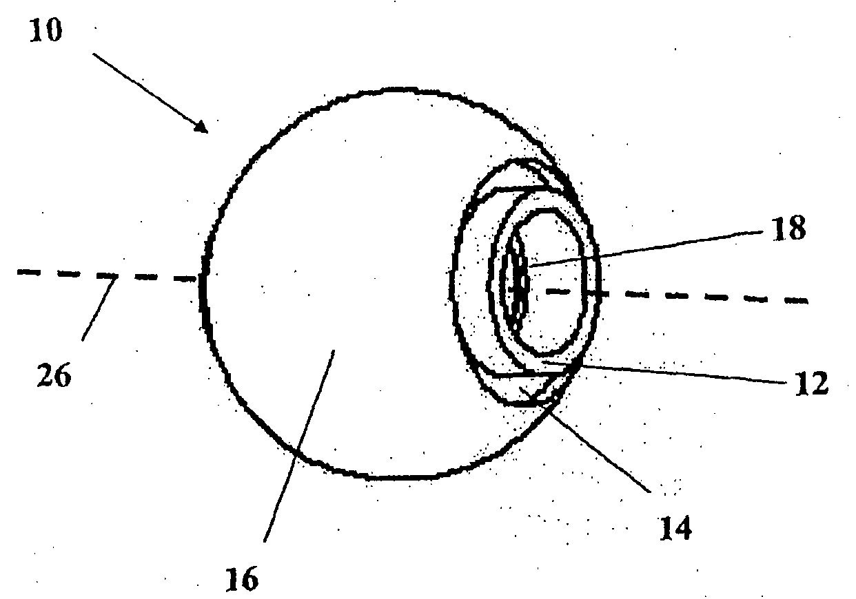
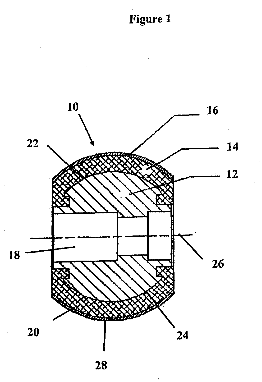
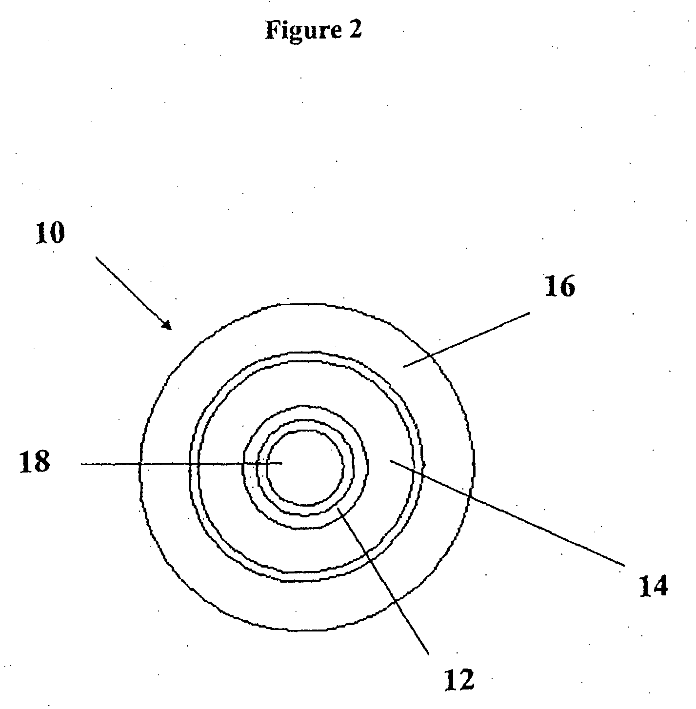
A polishing wheel (10) arranged to polish an article. The polishing wheel comprises a hub (12) pro-vided with an axial cavity (18) coaxial with an axis (26). The polishing wheel further comprises a substrate layer (14) being made of an elastomer material affixed to the hub (12) and coaxial with the axis (26). The substrate layer (14) has an outer surface (20) having a substantially symmetrical shape with respect to the axis (26). The polishing wheel (10) further comprises a continuous cover layer (16) affixed to the outer surface (20) and coaxial with the axis (26). The continuous cover layer (16) is made of an elastomer material covering substantially entirely the outer surface (20).

Description

FIELD OF INVENTION[0001]This invention relates to a polishing wheel arranged to polish an article, and more particularly an optical article, for example, an optical lens. This invention also relates to a method of manufacturing a polishing wheel, a method for polishing an article, and a computer program product for polishing an article.[0002]The article according to the invention may be made of, for example, glass, plastic or metal, such as, for example, a mould. The article of the invention includes any optical article for either concentrating or diverging light. Said optical article may be part of an optical system such as, for example, a telescope, a microscope or a camera.BACKGROUND OF INVENTION[0003]Optical lenses are used in ophthalmic devices such as eyeglasses and contact lenses and in precision instruments such as cameras, telescopes, microscopes, and range finders. These lenses are typically made by imparting a specific curvature on a first side of a transparent material s...

Claims


Application Information

Patent Timeline
IPC IPC(8): B23F21/03
CPCB24B13/01B24D5/00
Inventor SILVA, MARCRIALL, JAMES DANIELPADIOU, JEAN-MARCQUERE, LOIC
Owner ESSILOR INT CIE GEN DOPTIQUE
Why Eureka
Try Eureka