Dressing tool for the surface of an abrasive cloth and its production process

Inactive Publication Date: 2001-10-23
NEC ELECTRONICS CORP
View PDF24 Cites 30 Cited by
  • Summary
  • Abstract
  • Description
  • Claims
  • Application Information

AI Technical Summary

Benefits of technology

FIG. 5 Graph demonstrating the effect of a dressing tool of the present invention
FIG. 6 Graph demonstrating the effect of a dressing tool of the present invention
FIG. 7 Graphs dem

Problems solved by technology

First of all, the dressing tool has a short life. This is considered due to the wear of the nickel plating resulting from contact with the abrasive cloth which is easily made since the abrasive cloth is a hard materi

Method used


Image

  • Dressing tool for the surface of an abrasive cloth and its production process
  • Dressing tool for the surface of an abrasive cloth and its production process
  • Dressing tool for the surface of an abrasive cloth and its production process

Examples


first embodiment

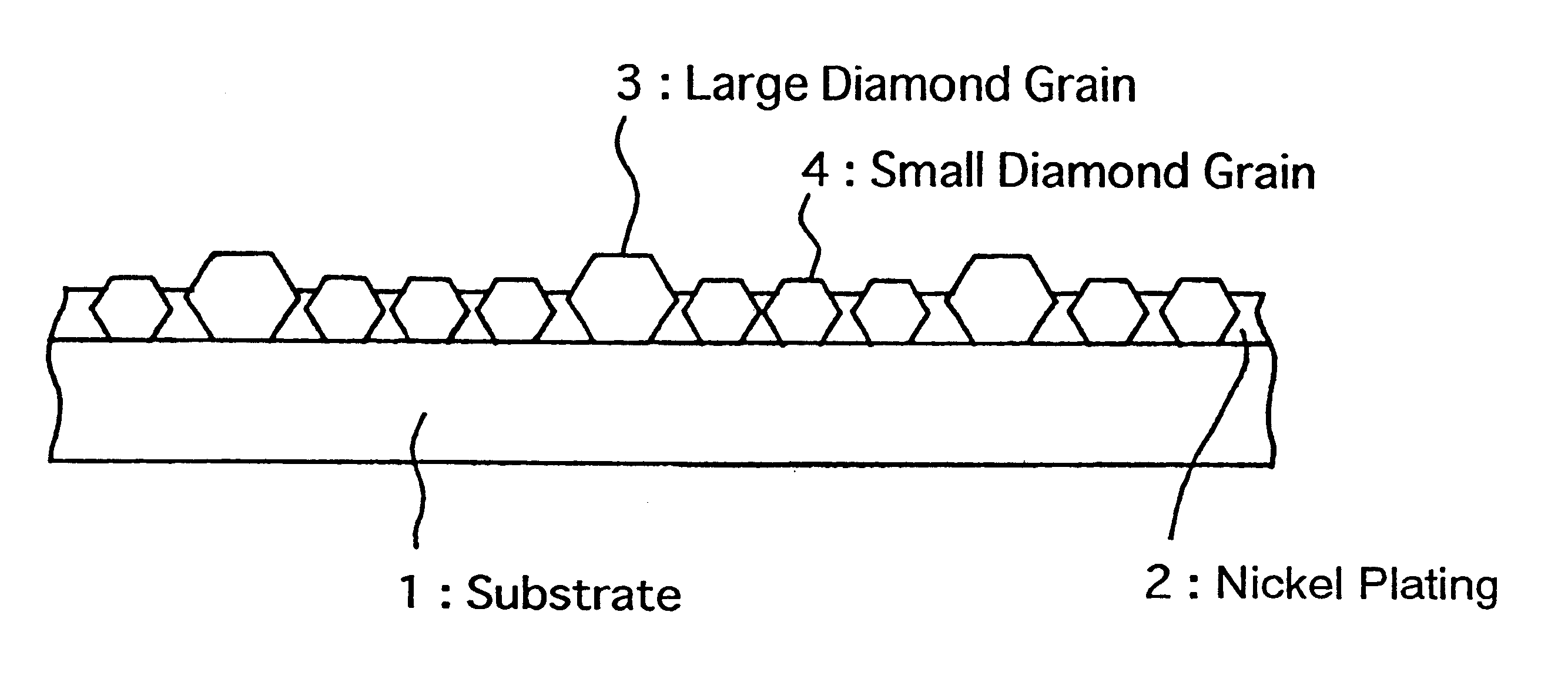
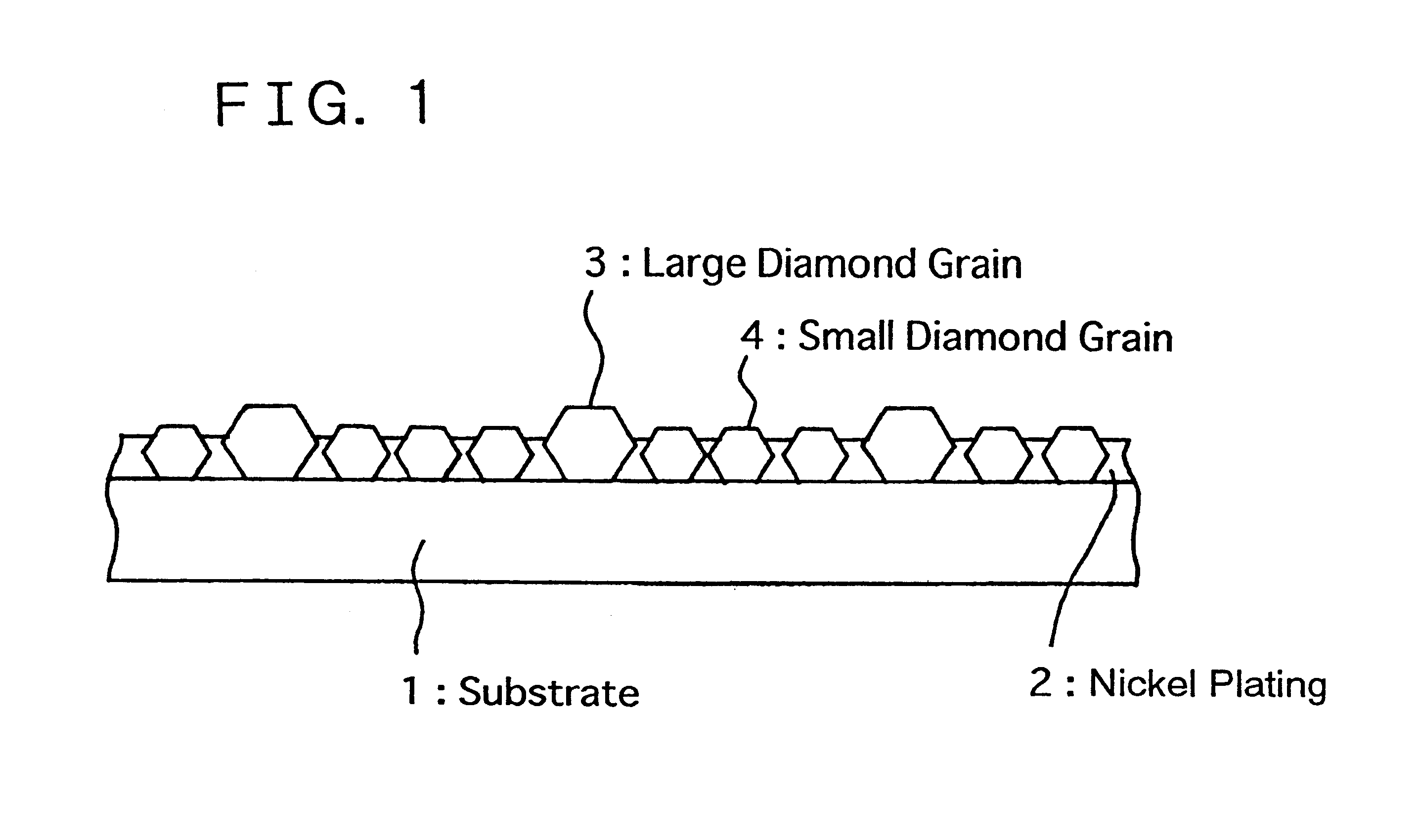
In a first embodiment of the present invention, as shown in FIG. 1, diamond grains of two or more groups classified in terms of an average particle diameter are fixed in mixture, and the upper end of small diamond grains 4 are also projected over nickel plating 2.

Desirably, in the mixture of the diamond grains, the number of large diamond grains 3 is equal to or less than the small diamond grains 4. Preferably, the number of the small grains is 2 to 20, or further 5 to 15, relative to the number "1 " of the large grains. Preferably, the large diamond grains 3 have diameters of 100 to 300 .mu.m, and small diamond grains 4 have 60 to 80% of the diameter of the large diamond grains 3.

Preferable thickness of the nickel plating 2 is 50 to 70% of the diameter of the large diamond grains 3.

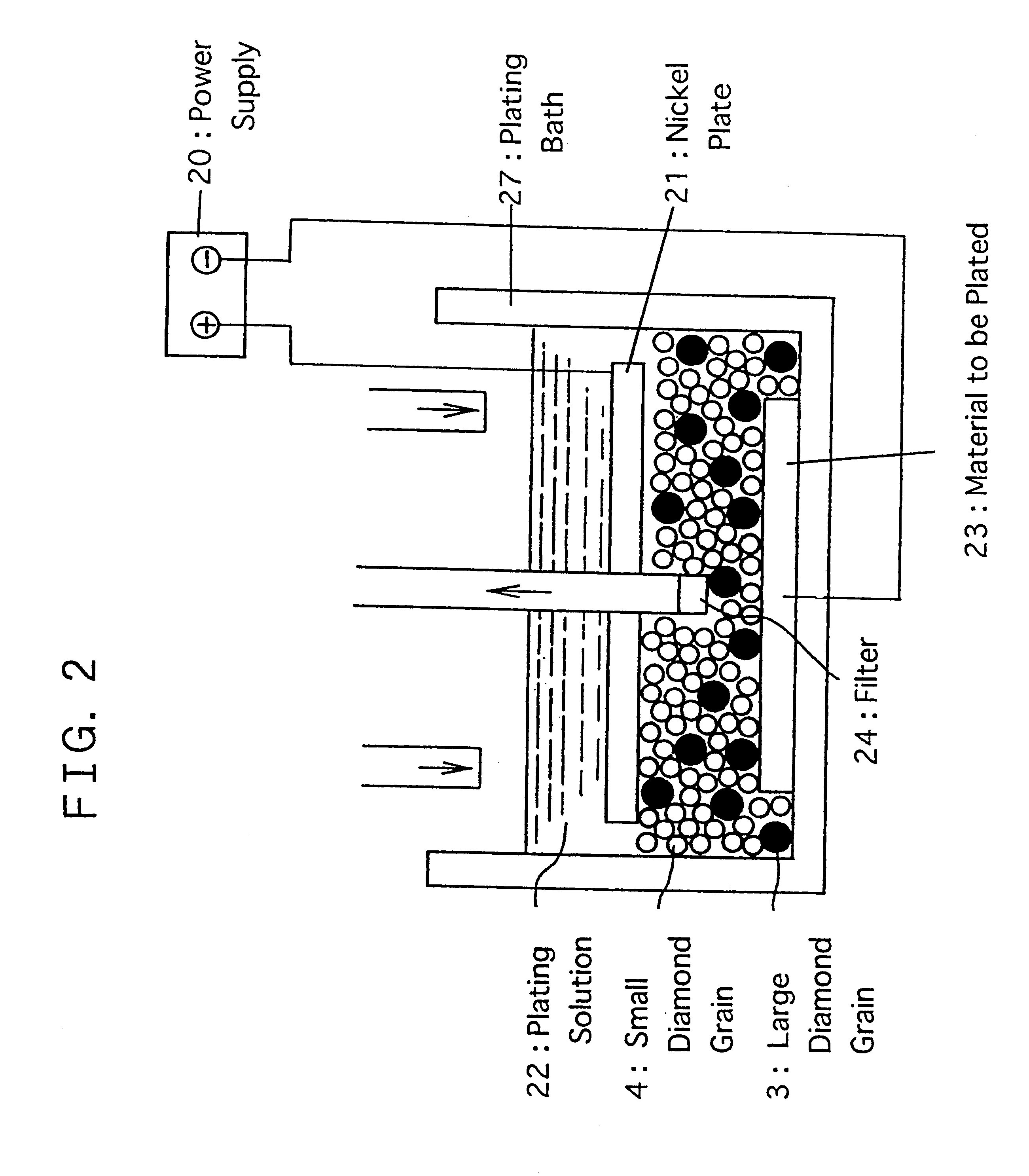
FIG. 2 shows a plating apparatus for use in preparing a dressing tool of the present invention for dressing the surface of an abrasive cloth.

The large and small diamond grains premixed in the predetermin...

examples

The present invention will be explained more in detail by the following examples in reference to the accompanying drawings.

FIG. 1 shows an exemplary dressing tool of the present invention. In this dressing tool, a disk substrate made of nickel alloy having a thickness of 2 mm and an outer diameter of 100 mm was provided with diamond grains having an average grain size of 180 .mu.m and another group of diamond grains having an average grain size of 130 .mu.m mixed in a ratio of 1:10. This mixing ratio was determined by filling a vessel having a unit volume with each group of diamond grains and estimated by the volume ratio of the resultant volumes. As a result, actual mixing ratio of diamond grains should be higher than the above mixing ratio. Then, the thickness of nickel plating was 110 .mu.m.

FIG. 2 shows a plating apparatus for use in preparing the exemplary dressing tool of the present invention. In a plating solution diamond grains having an average grain size of 180 .mu.m and a...

second embodiment

Now, a second embodiment of the present invention will be explained below in reference to the accompanying drawings.

FIG. 9 shows a second embodiment of a dressing tool of the present invention. This dressing tool essentially has a mixture of fixed diamond grains 3' having a predetermined average diameter with other fixed particles 6, smaller than the diamond grains, the upper end of which is projected over nickel plating 2.

Materials of the other particles include ZrO.sub.2, Al.sub.2 O.sub.3, Si.sub.3 N.sub.4, cubic boron nitride or ceramics, and hard plastics such as polyacetals (Delrin of DuPont), PET, polyester (Teflon) and polyurethane.

The production process of the second embodiment of the dressing tool of the present invention has the same steps of the first embodiment disclosed above. Namely, it includes steps of mixing the particles at the predetermined ratio, developing first thin plating, removing the floated particles and building up second plating to form an ultimate nicke...


PUM

PropertyMeasurementUnit
Linear densityaaaaaaaaaa
Thicknessaaaaaaaaaa
Diameteraaaaaaaaaa

Abstract

Onto the surface of a dressing tool for removing the clogging of an abrasive cloth, diamond grains of plural groups each having a different average particle diameter are subjected to be mixed and then fixed. In this state, the upper end of small diamond grains 4 is projected over nickel plating 2. Thereby foreign substances aggregated in the concave of the abrasive cloth are effectively removed and at the same time wearing the surface of the nickel plating 2 is prevented. Achieved are the stabilization of a polishing speed in polishing and the inhibition of dropping out diamond grains and wearing nickel plating in dressing.

Description

The present invention relates to a dressing tool for the surface of an abrasive cloth, more particularly to a dressing tool for dressing the surface of a polishing cloth for use in a mechanochemical polishing process.DISCUSSION ON THE RELATED ARTThe following considerations have been by the inventors during their eager investigations toward the present invention on the conventional techniques.Recently, the high integration of the semiconductor device, the focus margin of the exposing unit for transferring a pattern has gotten narrower and narrower so that the conventional flattening process of reflowing, coating such as Spin On Glass (SOG) coating or etching back is hard to provide for a wide range of flattening. In this respect, a Chemical Mechanical Polishing or mechanochemical polishing (hereinafter shortly referred to as "CMP") process for polishing a semiconductor substrate by mechanical and chemical actions has been mainly employed recently. A conventional polishing apparatus ...

Claims


Application Information

Patent Timeline
IPC IPC(8): B24B53/007B24B37/04B24B53/12B24D3/00B24D3/06C25D15/02
CPCB24B53/017B24B53/12B24D3/06C25D15/02
Inventor TORII, KOUJI
Owner NEC ELECTRONICS CORP
Why Eureka
Try Eureka