Automatic strand pulling machine for beam field

An automatic beam field technology, which is applied in the processing of building materials, construction, building construction, etc., can solve problems such as large deviations between tensile stress and elongation, construction that does not meet design specifications, and practical applications. , to achieve the effect of improving cutting efficiency, meeting the requirements of manual and automatic integration, and avoiding adverse wear and tear

Active Publication Date: 2021-08-10
中国建筑土木建设有限公司
View PDF7 Cites 0 Cited by
  • Summary
  • Abstract
  • Description
  • Claims
  • Application Information

AI Technical Summary

Problems solved by technology

A prestressed steel strand threading machine in the above-mentioned patent has the following disadvantages: Although the overall device has achieved the threading work of the steel strands, the prestressed steel cable is thrown by artificial single threading, and the construction does not meet the requirements of the design specification , and the whole bundle is difficult to achieve due to the limitation of the site, etc., resulting in a large deviation between the tension stress and the elongation in the prestressed tensioning operation, which cannot meet the practical application. The steel bundles are entangled in the beam body, resulting in the loss of prestress , a threat to engineering quality

Method used


Image

  • Automatic strand pulling machine for beam field
  • Automatic strand pulling machine for beam field
  • Automatic strand pulling machine for beam field

Examples


Embodiment 1

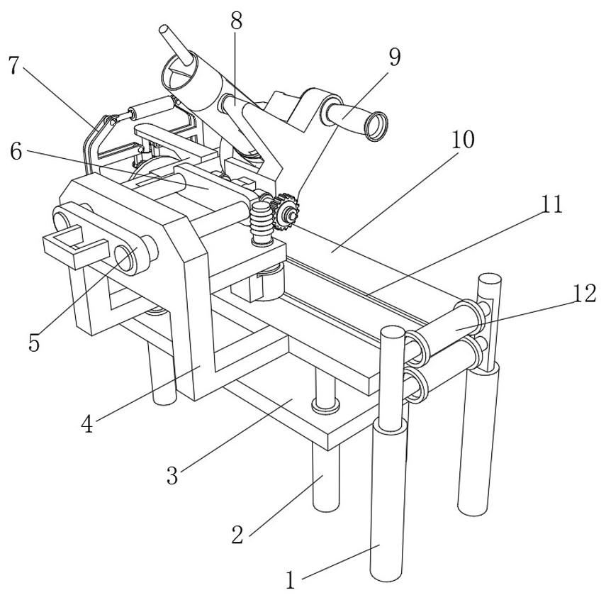
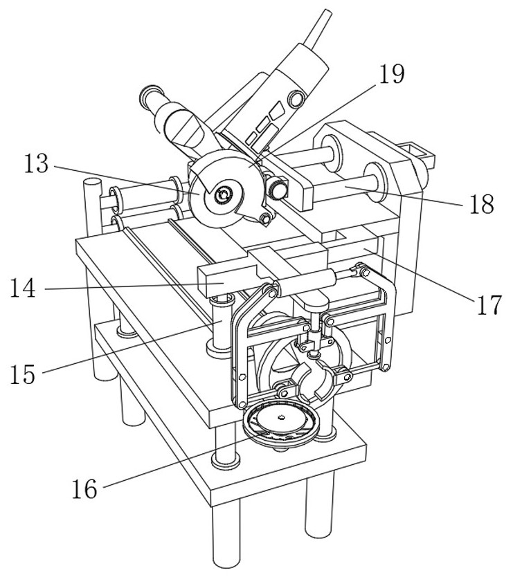
[0037] Beam field automatic beam threading machine, such as Figure 1-4 As shown, it includes a bottom plate 3, a workbench 10, two fixed columns 1 and a prestressed steel beam frame. Four pillars 2 run through the bottom of the bottom plate 3 and the workbench 10, and the tops of the two fixed columns 1 are on the opposite side of the outer wall. The push wheels 12 are respectively fixed by two rotating rods, the mounting frame 4 is fixed on one side of the workbench 10 by bolts, a support plate is provided on one side of the mounting frame 4, and a push-pull rotation mechanism is provided on the top of the mounting frame 4, and the push-pull One side of the rotating mechanism is fixed with a connecting plate 6 by bolts, and one side of the connecting plate 6 is rotatably connected with a fixed frame 8, and the outer wall of one side of the fixed frame 8 is fixed with a grinding wheel cutting machine 13 by bolts, and one side of the grinding wheel cutting machine 13 is passed ...

Embodiment 2

[0045] Beam field automatic beam threading machine, such as Figure 5 As shown, in order to avoid shifting when the steel bundle is pushed; this embodiment makes the following improvements on the basis of Embodiment 1: the outer wall of the side of the workbench 10 near the bottom of the binding mechanism 7 has a mounting groove, and the mounting groove The inner wall of the traction bucket 32 ​​is fixed with a traction bucket 32 ​​by bolts, and the outer wall of one side of the traction bucket 32 ​​is fixed with a mounting ring 34 through threads, and a hole 33 is opened on one side of the mounting ring 34, and a flexible pad is welded on the outer wall of the bottom side of the mounting ring 34 31; when the steel beam passes through the traction bucket 32, the tunnel 33 in the installation ring 34 can effectively limit and guide the steel beam, and the flexible pad 34 also avoids a large area of ​​wear during the steel beam pushing process, which promotes Integrity of the te...

Embodiment 3

[0047] Beam field automatic beam threading machine, such as Figure 6-7 As shown, in order to facilitate the installation of the steel beam, the prestressed steel beam frame includes three first brackets 35, twenty-four second brackets 36, twenty-four third brackets 37, and eight fourth brackets 38 , sixteen stop rods 39 and sixteen sliding seats 40, and three first brackets 35 are respectively fixed on one side of the workbench 10 by bolts, and every six second brackets 36 are respectively fixed on three sides by steel strands. One side of the first bracket 35, every three third brackets 37 are respectively fixed on the top side of every two second brackets 36 by steel strands, and every two fourth brackets 38 are respectively fixed on three sides by steel strands. At the bottom of the first bracket 36, each sliding seat 40 is welded to the top circumference side of each second bracket 36 respectively, and each stop rod 39 is slidably connected in each sliding seat 40; throug...


PUM


Abstract

The invention discloses an automatic strand pulling machine for a beam yard, and relates to the technical field of steel strand pulling of railway beam yards. In order to solve the problems of prestress loss and engineering quality, the automatic strand pulling machine specifically comprises a bottom plate, a workbench, two fixing columns and a prestress steel cable frame; four supporting columns penetrate through the bottom of the bottom plate and the bottom of the workbench, pushing wheels are fixed to the outer walls of the opposite sides of the top ends of the two fixing columns through two rotating rods correspondingly, a mounting frame is arranged on one side of the workbench, a supporting plate is arranged on one side of the mounting frame, a push-pull rotating mechanism is arranged at the top of the mounting frame, a connecting plate is arranged on one side of the push-pull rotating mechanism, one side of the connecting plate is rotationally connected with a fixing frame, and an abrasive wheel cutting machine is arranged on the outer wall of one side of the fixing frame; and the outer wall of one side of the supporting plate is connected with a fixing rod through an L-shaped fixing plate, and the bottom of the fixing rod is slidably connected with two guide wheels through a rotating shaft. One-time strand pulling of the steel strand is achieved, site discharging and placing are not needed, space is saved, and meanwhile the steel strand is prevented from being repeatedly transported and abraded.

Description

technical field [0001] The invention relates to the technical field of steel strand threading in railway beam yards, in particular to an automatic beam threading machine for beam yards. Background technique [0002] At present, in the construction of prestressed reinforced concrete structures, the steel strand threading construction is an indispensable operation process. The steel strand threading is to cut the prestressed steel strands according to the designed length and penetrate them into the pre-installed prestressed holes. inside the road. There are usually several to dozens of steel strands inserted into the prestressed tunnel. There are two methods of steel strand threading construction in the past: the first method is: artificial single threading method: the method is 4-6 people push the steel strands from one end to pass through the prestressed tunnel; the second method is: the overall beam threading method of the hoist: the method is to first cut the required num...

Claims


Application Information

Patent Timeline
Patent Type & Authority Applications(China)
IPC IPC(8): E04G21/12B21F11/00B21F23/00
CPCE04G21/12E04G21/122E04G21/123B21F11/00B21F23/00B21F23/005
Inventor 高树青包汉营郭志光李星
Owner 中国建筑土木建设有限公司
Why Eureka
Try Eureka