Mold inner wall spraying system for die casting equipment

A technology in the mold and equipment, applied in the direction of the injection device, etc., can solve the problems of spraying on the inner wall of the mold core and difficulty in atomizing the nozzle, and achieve the effect of rapid spraying and increased spraying range

Active Publication Date: 2022-06-17
上海恩耀机电有限公司
View PDF19 Cites 0 Cited by
  • Summary
  • Abstract
  • Description
  • Claims
  • Application Information

AI Technical Summary

Problems solved by technology

[0005] In order to improve the problem that it is difficult for the atomizing nozzle to spray the release agent on the inner wall of the mold core, the application provides a mold inner wall spraying system for die-casting equipment

Method used


Image

  • Mold inner wall spraying system for die casting equipment
  • Mold inner wall spraying system for die casting equipment
  • Mold inner wall spraying system for die casting equipment

Examples


Embodiment Construction

[0035] Attached to the following Figure 1-3 This application will be described in further detail.

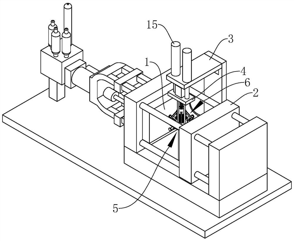
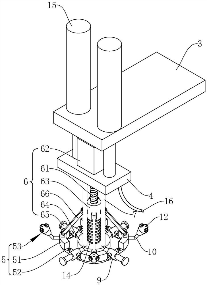
[0036] The embodiment of the present application discloses a mold inner wall spraying system of a die casting equipment. refer to figure 1 and figure 2 , the mold inner wall spraying system of the die-casting equipment includes a support plate 3 located above the movable mold core 1 and the static mold core 2. The static mold core 2 is fixedly erected on the die-casting equipment through the mold base, and the movable mold core 1 passes through the mold base. The sliding is arranged on the die casting equipment, and the movable mold core 1 can slide toward or away from the static mold core 2. The cavity formed after the movable mold core 1 and the static mold core 2 are pressed together is used for injection. The aluminum soup is die-cast as a casting.

[0037] refer to figure 1 and figure 2 , the support plate 3 is fixed above the movable mold core 1 and the static mold ...


PUM


Abstract

This application relates to a mold inner wall spraying system for die-casting equipment, and relates to the technical field of die-casting moulds. It includes a support plate located above the movable mold core and the static mold core. The connecting plate is connected with a spraying ring for spraying the inner wall of the mould, the diameter of the spraying ring is adjustable, and the connecting plate is provided with an expansion and contraction mechanism for adjusting the diameter of the spraying ring. The application has the effect of quickly spraying the release agent on the inner wall of the mold.

Description

technical field [0001] The present application relates to the technical field of die-casting molds, and in particular, to a mold inner wall spraying system of die-casting equipment. Background technique [0002] Die casting is a metal casting process. The traditional die casting process is mainly composed of four steps. These four steps include mold preparation, filling, injection, and falling sand. During the preparation process, lubricant needs to be sprayed into the mold cavity. In addition to helping control the temperature of the mold, it can also aid in casting release. The aluminum ingot is melted at high temperature to form an aluminum soup, and then the aluminum soup is injected into the mold through high pressure. The cavity of the mold applies high pressure to the aluminum soup, and the pressure will be maintained until the aluminum soup solidifies to form a casting. Finally, the mold is opened and the push rod pushes the The casting is pushed out of the mold. T...

Claims


Application Information

Patent Timeline
Patent Type & Authority Patents(China)
IPC IPC(8): B05B13/06B05B15/68
CPCB05B13/0636B05B15/68
Inventor 庞永王辉军
Owner 上海恩耀机电有限公司
Why Eureka
Try Eureka