Small and special electric machine machining equipment
A technology for processing equipment and micro-motors, applied in metal processing equipment, metal processing mechanical parts, manufacturing tools, etc., can solve the problem of incapable of automatic and fast batch processing of motor stator plates.
- Summary
- Abstract
- Description
- Claims
- Application Information
AI Technical Summary
Problems solved by technology
Method used
Image
Examples
specific Embodiment approach 1
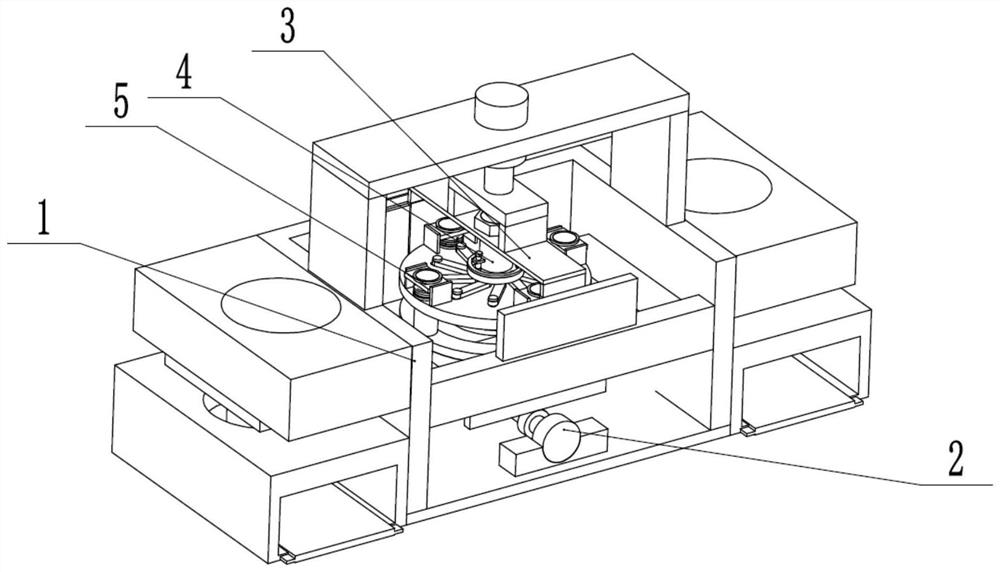
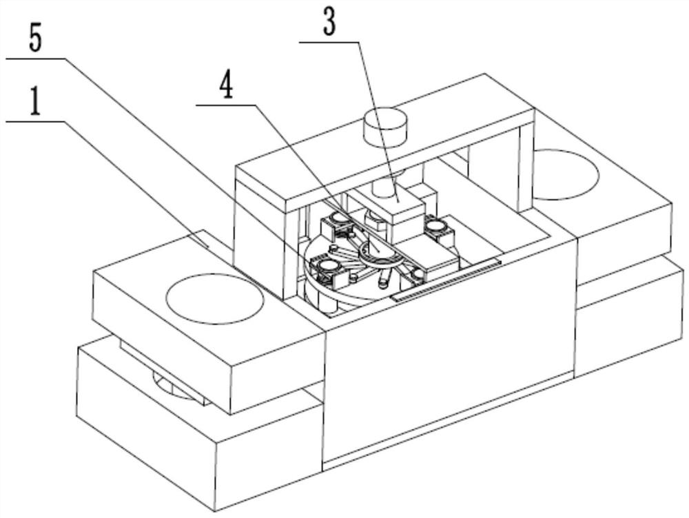
[0030] Such as Figure 1 to Figure 10 As shown, a micro-special motor processing equipment includes a stator plate processing frame 1, a reciprocating intermittent conveyor 2, a hydraulic propeller 3, a stator slot cutting regulator 4, and a cutting and tightening device 5. The reciprocating intermittent conveyor 2 Left and right reciprocating sliding connection on the stator plate processing frame 1, the hydraulic propeller 3 is intermittently longitudinally sliding connected to the middle end of the stator plate processing frame 1, and the stator slot cutting regulator 4 is connected to the hydraulic propeller 3 through screw fit On, the cutting tensioner 5 is fixedly connected to the stator slot cutting regulator 4 . The stator plate is stacked on the stator plate processing frame 1, and the stator plate is pushed to the lower end of the hydraulic propeller 3 through the reciprocating intermittent movement of the reciprocating intermittent conveyor 2; the stator slot cuttin...
specific Embodiment approach 2
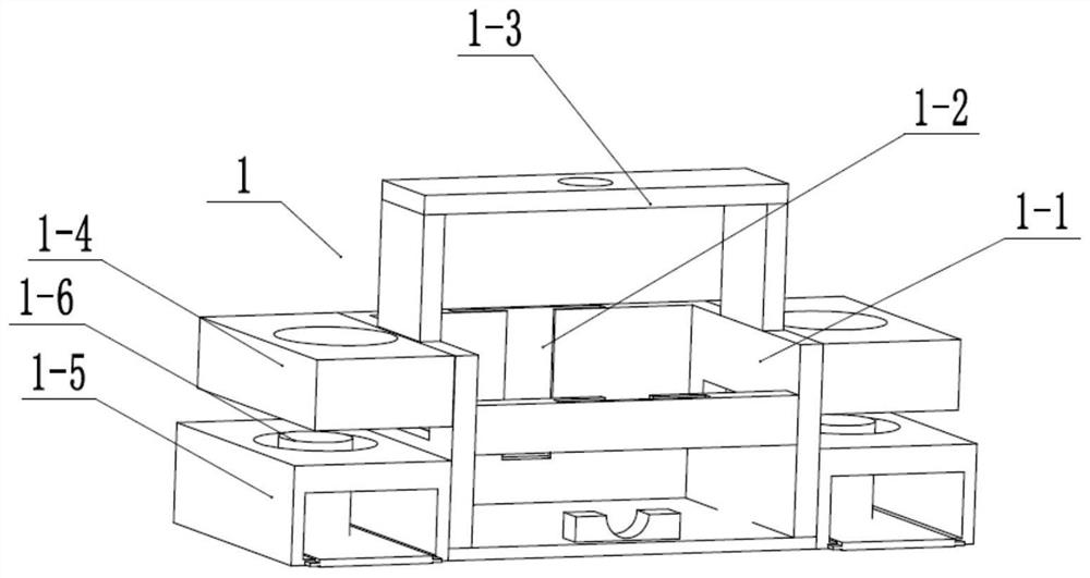
[0032] Such as Figure 1 to Figure 10As shown, this embodiment further explains the first embodiment. The stator plate processing frame 1 includes a central processing frame 1-1, two limit longitudinal chute 1-2, a hydraulic cylinder propulsion frame 1-3, two One stator plate stacking box 1-4, two molded stator recovery boxes 1-5 and interference cylinder 1-6, internal fixing carrier plate 1-7, two transverse chute 1-8 and miscellaneous materials falling round hole 1- 9. The front and rear ends of the inner wall of the central processing frame 1-1 are respectively longitudinally provided with two limiting longitudinal chute 1-2, the hydraulic cylinder propulsion frame 1-3 is fixedly connected to the upper end of the central processing frame 1-1, and two stator plates Stacking boxes 1-4 are respectively fixedly connected to the upper sides of the two ends of the central processing frame 1-1, two forming stator recovery boxes 1-5 are respectively fixedly connected to the lower s...
specific Embodiment approach 3
[0034] Such as Figure 1 to Figure 10 As shown, this embodiment will further illustrate the second embodiment. The reciprocating intermittent conveyor 2 includes a frequency conversion drive motor 2-1, two sliding tooth plates 2-2, two loading pallets 2-3, a drop Slot 2-4 and two sliding push baffles 2-5, the variable frequency drive motor 2-1 is fixedly connected to the lower end of the inner wall of the central processing frame 1-1 through the motor fixing seat, and the two sliding tooth plates 2-2 are respectively engaged by gears The transmission is connected to the transmission shaft of the variable frequency drive motor 2-1, and the two sliding tooth plates 2-2 are respectively slidingly connected in the two transverse chute 1-8, and the lower ends of the two supporting plates 2-3 are fixedly connected to two The sliding tooth plate 2-2 and the falling groove 2-4 are arranged between the two loading pallets 2-3, and the two sliding push baffles 2-5 are respectively fixed...
PUM
 Abstract
Description
Claims
Application Information
 - R&D
- Intellectual Property
- Life Sciences
- Materials
- Tech Scout
- Unparalleled Data Quality
- Higher Quality Content
- 60% Fewer Hallucinations
Browse by: Latest US Patents, China's latest patents, Technical Efficacy Thesaurus, Application Domain, Technology Topic, Popular Technical Reports.
© 2025 PatSnap. All rights reserved.Legal|Privacy policy|Modern Slavery Act Transparency Statement|Sitemap|About US| Contact US: help@patsnap.com


