
Branch bus contact seat assembly structure

A technology of assembly structure and branch busbar, which is applied in the direction of coupling devices, parts of connecting devices, devices for joining/disconnecting connecting parts, etc., can solve problems such as conductive performance damage, conductor heavy stress, spring finger deformation, etc. To achieve the effect of ensuring contact conductivity, relieving pressure, and avoiding excessive deformation

Pending Publication Date: 2021-08-13
湖南长高电气有限公司
View PDF0 Cites 0 Cited by
  • Summary
  • Abstract
  • Description
  • Claims
  • Application Information

AI Technical Summary

Problems solved by technology

[0002] In the conventional contact seat, the spring contact fingers are fixed. When the conductor is inserted, the force is often eccentric due to the conductor being too heavy or the thrust is too large, which will cause the spring contact fingers to deform, resulting in damage to the electrical conductivity.

Method used


Image

  • Branch bus contact seat assembly structure
  • Branch bus contact seat assembly structure
  • Branch bus contact seat assembly structure

Examples


Embodiment Construction

[0024] Embodiments of the present invention are described in detail below, and examples of the embodiments are shown in the drawings, wherein the same or similar reference numerals denote the same or similar elements or elements having the same or similar functions throughout. The embodiments described below by referring to the figures are exemplary only for explaining the present invention and should not be construed as limiting the present invention.

[0025] In the description of the present invention, it should be understood that the orientation descriptions, such as up, down, front, back, left, right, etc. indicated orientations or positional relationships are based on the orientations or positional relationships shown in the drawings, and are only In order to facilitate the description of the present invention and simplify the description, it does not indicate or imply that the device or element referred to must have a specific orientation, be constructed and operated in ...


PUM


Abstract

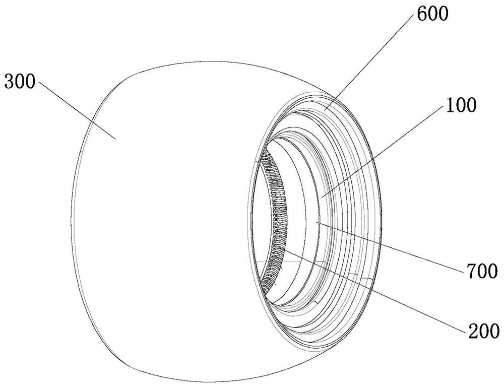
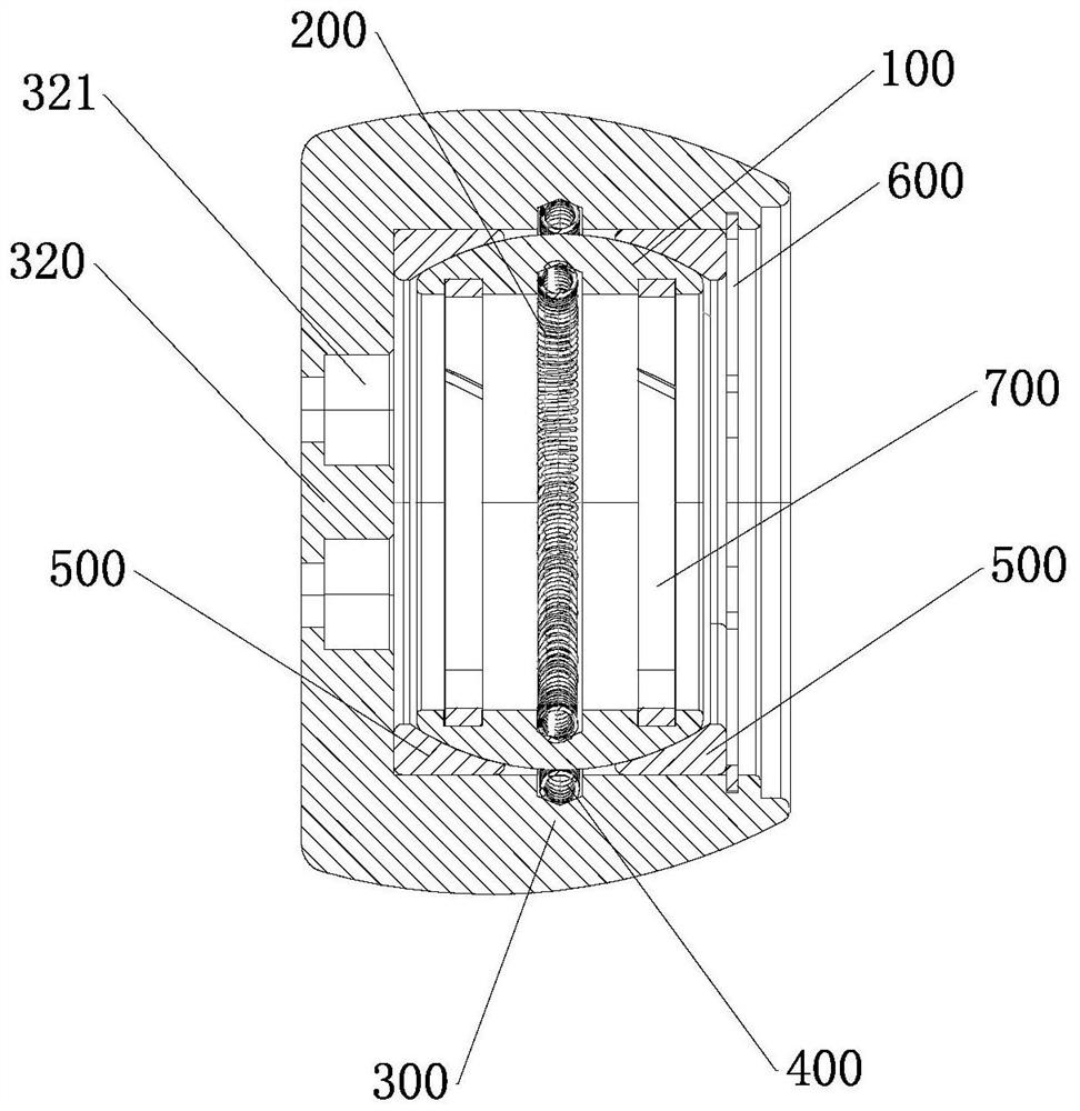
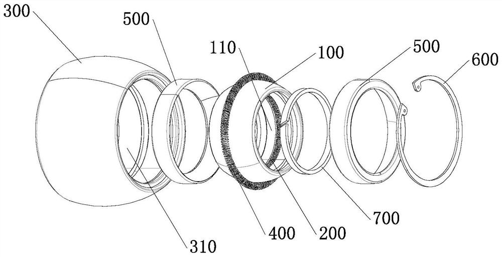
The invention discloses a branch bus contact seat assembly structure, which comprises a tubular contact finger mounting seat and a contact head. The contact finger mounting seat is provided with a plug-in mounting pipeline; the outer wall of the contact finger mounting seat is in an arc shape arched from two ends to the middle; an annular first spring contact finger mounting groove is formed in the plug-in mounting pipeline; a first spring contact finger is arranged in the first spring contact finger mounting groove; and the inner diameter of the first spring contact finger is smaller than that of the plug-in mounting pipeline. The contact seat is provided with an assembly hole. One end of the assembly hole is provided with an insertion port, and the other end of the assembly hole is provided with a baffle plate. The assembly hole is internally provided with an arc-shaped groove matched with the outer wall of the contact finger mounting seat, the groove bottom of the arc-shaped groove is provided with an annular second spring contact finger mounting groove, and the second spring contact finger mounting groove is internally provided with a second spring contact finger. The contact finger mounting seat is mounted in the arc-shaped groove, and the outer wall of the contact finger mounting seat is in contact connection with the second spring contact finger.

Description

technical field [0001] The invention relates to a connecting part of electrical equipment, in particular to an assembly structure of a branch bus contact seat. Background technique [0002] In a conventional contact seat, the spring finger is fixed, and when the conductor is inserted, the force is often eccentric due to the conductor being too heavy or the thrust is too large, resulting in deformation of the spring finger, resulting in damage to the electrical conductivity. Contents of the invention [0003] The present invention aims to solve at least one of the technical problems existing in the prior art. For this reason, the present invention proposes an assembly structure of the branch bus contact seat, which can solve the damage to the spring contact fingers when the conductor is inserted into the contact seat. [0004] An assembly structure of a branch bus contact seat according to the present invention, comprising: [0005] The contact finger mounting seat is tub...

Claims


Application Information

Patent Timeline
Patent Type & Authority Applications(China)
IPC IPC(8): H01R13/639H01R13/62
CPCH01R13/62H01R13/639
Inventor 赵海波张建成李科峰
Owner 湖南长高电气有限公司
Learn More