
Traffic flow detector of automotive vehicle and operating method of traffic flow detector

A traffic flow and detection device technology, applied in the field of motor vehicle traffic flow detection devices, can solve the JCF series vehicle detection developed in Denmark, the JZJ vehicle detector developed by Dandong Electronics Research Institute, and the geomagnetic field developed by the Chongqing Highway Institute of the Ministry of Communications The vehicle detector and the Wuxi Institute of the Ministry of Public Security have developed problems such as low detection accuracy and poor reliability, and achieved the effects of high impact resistance, high detection accuracy, and good reliability

Active Publication Date: 2013-08-28
DALIAN MARITIME UNIVERSITY
View PDF7 Cites 0 Cited by
  • Summary
  • Abstract
  • Description
  • Claims
  • Application Information

AI Technical Summary

Problems solved by technology

At present, a variety of detection devices related to motor vehicle traffic flow have been developed at home and abroad, such as: ST series and VC series vehicle detectors developed in the UK, JCF series vehicle detection developed in Denmark, and JZJ type vehicle detection developed by Dandong Electronics Research Institute. One of the common characteristics of the above-mentioned detection devices is that they use electronic coil detectors and need to be buried underground in advance. The main disadvantages are poor reliability, low detection accuracy, short life and inconvenient maintenance.

Method used


Image

  • Traffic flow detector of automotive vehicle and operating method of traffic flow detector
  • Traffic flow detector of automotive vehicle and operating method of traffic flow detector
  • Traffic flow detector of automotive vehicle and operating method of traffic flow detector

Examples


Embodiment Construction

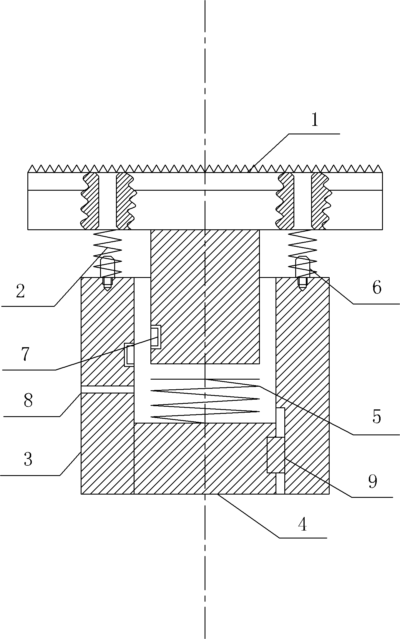
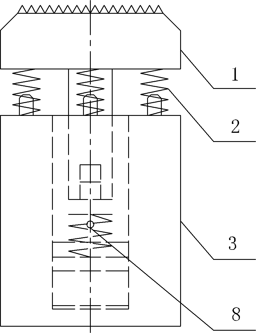
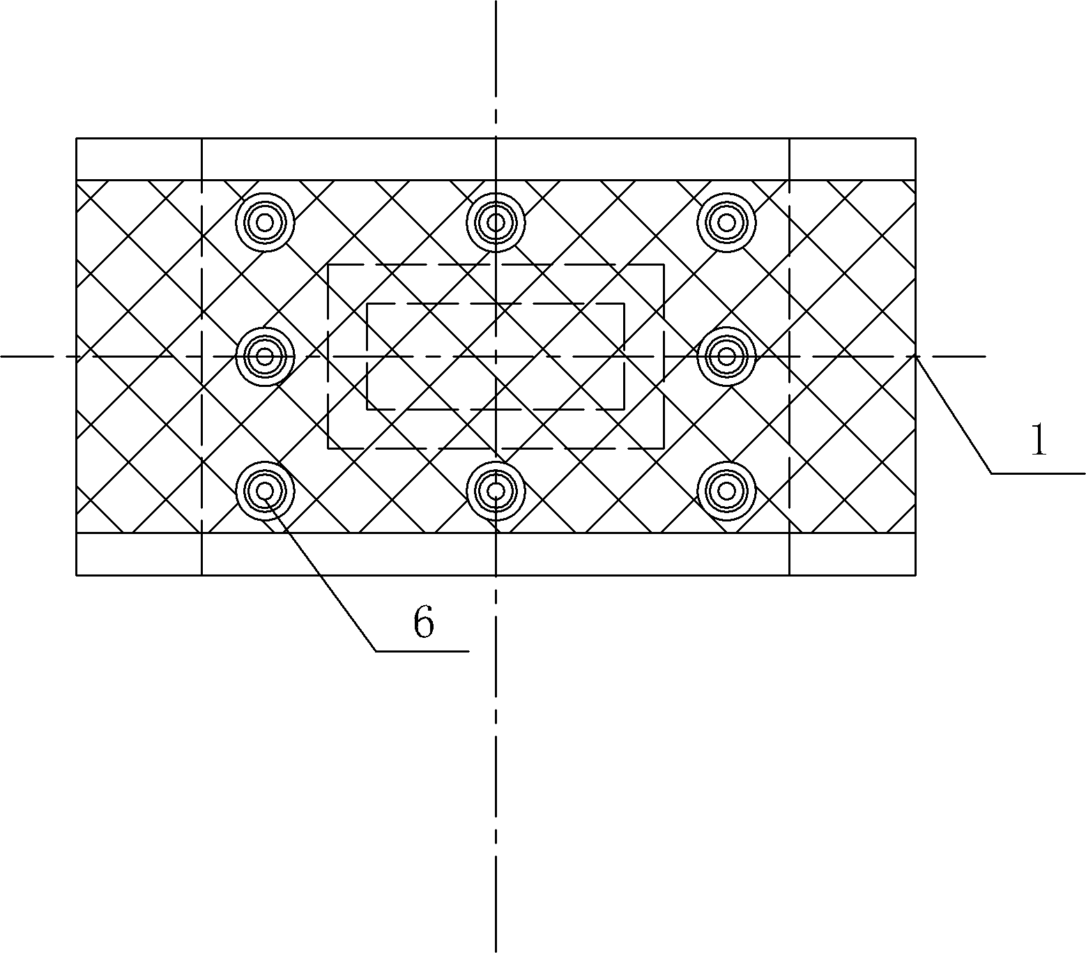
[0027] The present invention will be further described below in conjunction with the accompanying drawings. Such as Figure 1-3 As shown, a motor vehicle traffic flow detection device includes a T-shaped column 1, a buffer spring 2, a support sleeve 3, a base plate 4, an electronic coil detector 5 and a microprocessor, and also includes an embedded Hall sensor 7; Both sides of the column head of the T-shaped column 1 are respectively installed on the support sleeve 3 through the buffer spring 2, and the described buffer spring 2 is installed on the support sleeve 3 through the positioning pin 6, and the support sleeve 3 and The bottom plate 4 is slidably connected by a key 9, and the outside of the T-shaped post 1 and the inner side of the support sleeve 3 each have a rectangular through slot, and the outer rectangular through slot of the T-shaped post 1 post is installed with Embedded Hall sensor 7, the inner rectangular through groove of the support sleeve 3 is embedded wit...


PUM


Abstract

The invention discloses a traffic flow detector of an automotive vehicle and a detecting method of the traffic flow detector. The traffic flow detector of the automotive vehicle comprises a T-shaped column, buffer springs, a supporting sleeve, a base plate, an electronic coil detector, a microprocessor and an embedded Hall sensor, wherein both sides of a head of the T-shaped column are respectively arranged on the supporting sleeve by the buffer springs, a rectangular through groove on the outer side of a pole of the T-shaped column is provided with the embedded Hall sensor, a magnet is embedded in a rectangular through groove on the inner side of the supporting sleeve, and the electronic coil detector is arranged between the base plate and the pole of the T-shaped column. According to the invention, the parallel detection is preformed on the flow of automotive vehicles on a motorway simultaneously by employing the electronic coil detector and the embedded Hall sensor so as to form two detection manners which are complementary and checked with each other, thus the detection precision is higher and the reliability is better. According to the traffic flow detector and the operation method disclosed by invention, the gravity directly acted on the electronic coil detector can be greatly relieved and the service life of a detection coil can be effectively prolonged.

Description

technical field [0001] The invention relates to a traffic flow detection device, in particular to a motor vehicle traffic flow detection device and a detection method thereof. Background technique [0002] With the rapid increase of urban traffic flow, the difficulty of urban traffic management is gradually increasing. At present, many countries in the world, including developed countries, generally adopt intelligent traffic control systems. In order to meet the needs of intelligent traffic control systems for traffic flow data, most countries generally use electronic coil detectors with high detection accuracy as traffic flow control systems. The main equipment for collection. The equipment is usually buried 50-70m underground from the stop line at the intersection. Because a large amount of traffic passes through the place where the coil is buried, the service life of the coil is relatively short, generally about 10 years. Therefore, how to prolong the service life of th...

Claims


Application Information

Patent Timeline
Patent Type & Authority Patents(China)
IPC IPC(8): G08G1/065G08G1/042
Inventor 张赫王立鼎王炜张常功姚迪
Owner DALIAN MARITIME UNIVERSITY
Learn More