Round particle high tower granulation method and double-layer ventilation material receiving device thereof
A material receiving device and high-tower granulation technology, which is applied in the direction of liquid separation into beads and granulation, can solve the problems of low pass rate, unguaranteed product quality, and unrounded particles, so as to ensure ventilation and avoid fertilizer particles from scattering Effect
- Summary
- Abstract
- Description
- Claims
- Application Information
AI Technical Summary
Problems solved by technology
Method used
Image
Examples
Embodiment 1
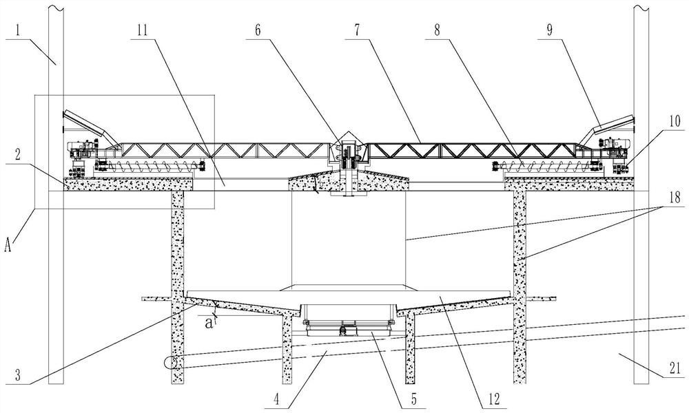
[0031] like figure 1 As shown, the double-layer ventilation and material receiving device includes an upper material receiving table 2, the upper material receiving table 2 is a circular structure, and the upper material receiving table 2 is provided with a ventilation blanking port 11 and a ventilation blanking port 11 The matching screw receiving mechanism has a lower receiving table 3 at the bottom of the upper receiving table 2, such as Figure 4 As shown, a central ventilation hole 16 is arranged in the middle of the lower receiving table 3, a strip discharge port 15 is arranged on the lower receiving table 3, a slewing bearing 5 is arranged at the central ventilation hole 16, and the fixed ring of the slewing bearing 5 is The lower receiving table 3 is fixedly connected, the slewing ring of the slewing bearing 5 is matched with the output end of the drive mechanism, and the slewing ring of the slewing bearing 5 is provided with one or more rotating scrapers 12 matched wi...
Embodiment 2
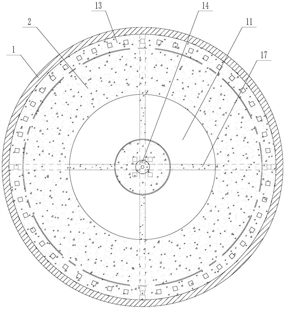
[0034] like image 3 As shown, the ventilation blanking port 11 is an annular structure, and a plurality of support beams 17 are arranged on the ventilation blanking port 11 of the annular structure. The connection is fixed; the support beam 17 provides strength for the upper receiving table 2 on both sides of the ventilation blanking port 11, and at the same time facilitates the passage of the air intake.
[0035] The included angle a between the lower receiving table 3 and the horizontal plane is 5-10°, and the included angle a is preferably 7°, and a protective ventilation net is provided between the lower receiving table 3 and the upper receiving table 2 outside the ventilation blanking port 11 18. The bucket-type lower receiving table 3 is used to facilitate the flow of fertilizer particles, and the protective ventilation net 18 is arranged below the annular ventilation opening 11 to prevent the falling fertilizer particles from scattering to the outside of the lower rec...
Embodiment 3
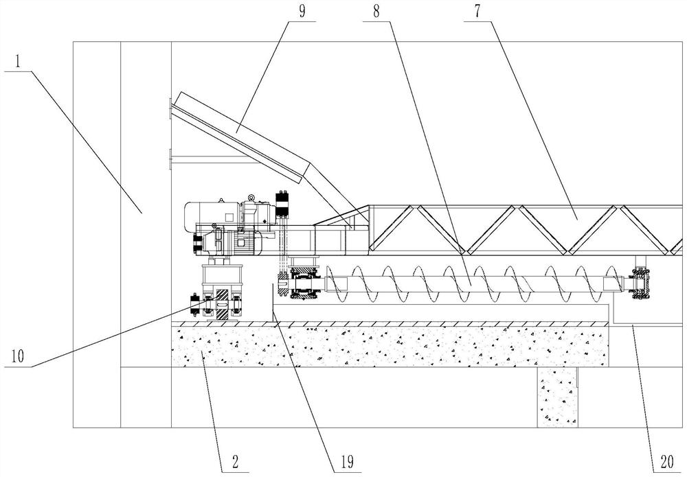
[0037] like figure 1 and figure 2 As shown, the screw receiving mechanism includes a central rotor 6, the central rotor 6 is installed in the middle of the upper receiving table 2, the upper receiving table 2 is provided with a main beam 7, the main beam 7 is rotated and installed on the central rotor 6, and the main beam 7 A rotating sports car 10 is respectively provided between the two ends and the upper receiving table 2, the upper receiving table 2 is provided with a sports car track 13 which is matched with the rotating sports car 10, the inner side of the rotating sports car 10 is provided with a material stop ring 19, and the bottom of the main beam 7 One end or both ends are provided with a screw conveyor 8 and a girder scraper 20. The screw conveyor 8 is arranged between the stopper ring 19 and the periphery of the ventilation blanking port 11, and the girder scraper 20 is arranged at the periphery of the ventilation blanking port 11 and the upper receiving material...
PUM
| Property | Measurement | Unit |
|---|---|---|
| diameter | aaaaa | aaaaa |
Abstract
Description
Claims
Application Information
 - R&D
- Intellectual Property
- Life Sciences
- Materials
- Tech Scout
- Unparalleled Data Quality
- Higher Quality Content
- 60% Fewer Hallucinations
Browse by: Latest US Patents, China's latest patents, Technical Efficacy Thesaurus, Application Domain, Technology Topic, Popular Technical Reports.
© 2025 PatSnap. All rights reserved.Legal|Privacy policy|Modern Slavery Act Transparency Statement|Sitemap|About US| Contact US: help@patsnap.com


