An automatic fire extinguishing device for corridor fire detection

A technology for detecting automatic and fire extinguishing devices, applied in fire rescue, fire alarms relying on smoke/gas effects, etc., can solve problems such as personal and property losses, inconvenient handling of electric vehicles, and inability of residents to find out in time, so as to improve The effect of fire extinguishing effect

Active Publication Date: 2022-03-08
帕沃电子技术有限公司
View PDF5 Cites 2 Cited by
  • Summary
  • Abstract
  • Description
  • Claims
  • Application Information

AI Technical Summary

Problems solved by technology

[0002] With the development of society, people rely more and more on electrical equipment in their daily life. For example, many people choose to use electric vehicles for daily commuting. In newly built communities, it is more convenient for electric vehicles to have special charging areas. It is inconvenient to carry the car upstairs. Many residents will privately pull the wires to the first floor to charge the electric car in the corridor. If there is a short circuit caused by a bad wire or plug, it will cause a fire. It is necessary to find out the fire and put it out in time.
[0003] However, most of the corridors of existing old buildings do not have equipment that can respond to fires in time. After the electric vehicle catches fire at night, the residents cannot find it in time. The timing of escape and fire extinguishing has caused great losses to people and property, so there is a need for an automatic fire extinguishing device for corridor fire detection

Method used


Image

  • An automatic fire extinguishing device for corridor fire detection
  • An automatic fire extinguishing device for corridor fire detection
  • An automatic fire extinguishing device for corridor fire detection

Examples


Embodiment Construction

[0022] The following will clearly and completely describe the technical solutions in the embodiments of the present invention with reference to the accompanying drawings in the embodiments of the present invention. Obviously, the described embodiments are only some, not all, embodiments of the present invention. Based on the embodiments of the present invention, all other embodiments obtained by persons of ordinary skill in the art without making creative efforts belong to the protection scope of the present invention.

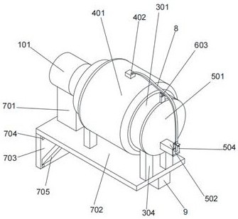
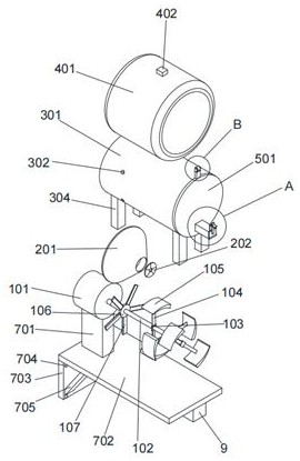
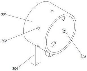
[0023] see Figure 1-Figure 5, the present invention provides a technical solution: an automatic fire extinguishing device for fire detection in corridors, including a motor 101, a connecting shaft 102 is fixedly connected to the front side of the rotating shaft of the motor 101, and a central block 103 is fixedly connected to the peripheral side of the connecting shaft 102. It is characterized in that: the upper and lower surfaces of the central block 103 are...


PUM


Abstract

The invention discloses an automatic fire extinguishing device for corridor fire detection and relates to the technical field of fire emergency equipment. The automatic fire extinguishing device for fire detection in corridors includes a motor, a connecting shaft is fixedly connected to the front side of the rotating shaft of the motor, and a central block is fixedly connected to the circumferential side of the connecting shaft, and is characterized in that: the upper and lower surfaces of the central block are fixedly connected with a connecting shaft. Rod, the side of one end of the connecting rod away from the central block is fixedly connected with a stirring block, and the circumferential side of the connecting shaft is fixedly connected with a fan blade, the fan blade is located at the rear side of the central block, and the front side of the fan blade is provided with an air inlet plate, which solves the problem of Most of the corridors of existing old buildings do not have the equipment to deal with fire in time. After the electric vehicle catches fire at night, the residents cannot find it in time. They will not find it until the flame or smoke diffuses upstairs. At this time, the best escape has been missed. And the timing of fire extinguishing has caused a lot of damage to people and property.

Description

technical field [0001] The invention relates to the technical field of fire emergency equipment, in particular to an automatic fire extinguishing device for corridor fire detection. Background technique [0002] With the development of society, people rely more and more on electrical equipment in their daily life. For example, many people choose to use electric vehicles for daily commuting. In newly built communities, it is more convenient for electric vehicles to have special charging areas. It is inconvenient to carry the car upstairs. Many residents will privately pull the wires to the first floor to charge their electric cars in the corridor. If there is a short circuit caused by a bad connection of the wire or plug, it will cause a fire. It is necessary to find out the fire and put it out in time. [0003] However, most of the corridors of existing old buildings do not have equipment that can respond to fires in time. After the electric vehicle catches fire at night, th...

Claims


Application Information

Patent Timeline
Patent Type & Authority Patents(China)
IPC IPC(8): A62C3/02A62C31/28A62C31/00A62C37/00G08B17/10
CPCA62C3/0214A62C31/28A62C31/00A62C37/00G08B17/10
Inventor 毕贞磊王申杰
Owner 帕沃电子技术有限公司
Why Eureka
Try Eureka