Novel paint cup

A paint cup, a new type of technology, applied in decorative arts, painting tools, etc., can solve the problems of being unable to tighten the palm and the cup body, unable to maintain the adjustment position stably, and achieve the effect of safe painting from the ground

Pending Publication Date: 2021-08-17
NINGBO BEILUN GELEI PLASTIC PROD
View PDF1 Cites 0 Cited by
  • Summary
  • Abstract
  • Description
  • Claims
  • Application Information

AI Technical Summary

Problems solved by technology

[0004] In view of the above situation, in order to overcome the above prior art, the adjustable handle of the paint cup is adjusted according to the shape of the hand, and after the adjustment is completed, it cannot be kept at the adjusted position stably, resulting in the inability to align the palm of the operator with the cup body. To solve the problem of tightness, the purpose of the present invention is to provide a new type of paint cup that can always be attached to the back of the palm of the operator so as to bind the palm of the operator more tightly on the outer wall of the cup body

Method used


Image

  • Novel paint cup
  • Novel paint cup
  • Novel paint cup

Examples


Embodiment 1

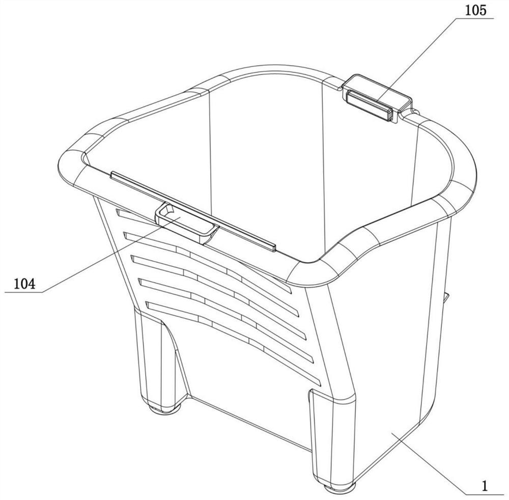
[0034] Such as Figure 1 to Figure 3As shown, a new type of paint cup, the same as the prior art, it includes a cup body 1, the rear side of the cup body 1 is provided with a handle, especially, the handle is a flexible handle, which includes one end as a fixed end and the other end The adjustment belt 2 is a free end, and the fixed end of the adjustment belt 2 is connected with the cup body 1. In addition, a retractable belt mechanism opposite to the adjustment belt 2 is provided on the rear side of the cup body 1, and the retractable belt mechanism is connected with the adjustment belt 2 at the same time. There is a certain distance between the fixed ends of the cup body. This part of the distance is used for inserting the palm of the operator in a posture capable of holding the cup body 1. Here, the palm is defined as the holding hand. The free end of the adjustment belt 2 is self-retractable. One side of the mechanism passes through and extends to the outside of the other ...

Embodiment 2

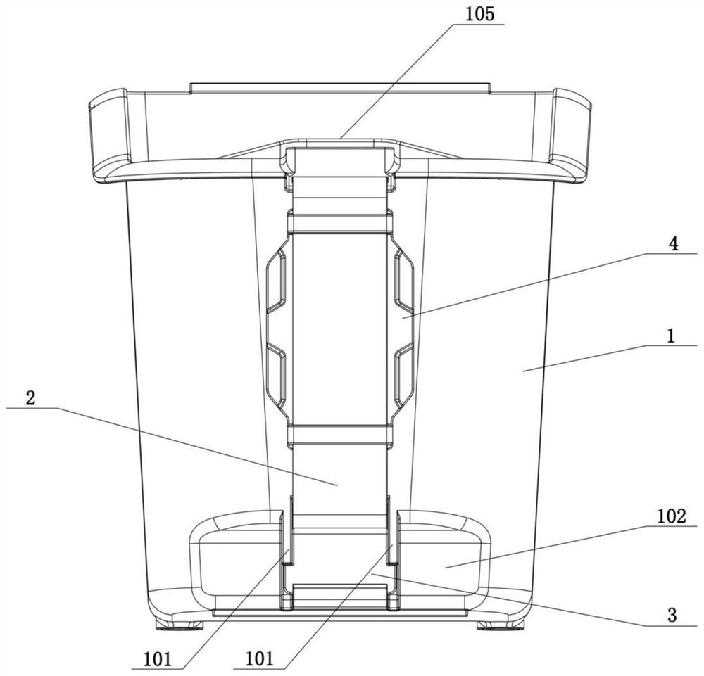
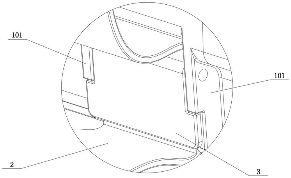
[0036] Such as figure 2 and image 3 As shown, the above-mentioned retractable belt mechanism specifically includes an adjustment block 3, and a boss 101 protruding outward is formed on the cup body 1 located on the left and right sides of the adjustment block 3, and the adjustment block 3 and the boss 101 are connected together. It is connected in a rotatable manner, and when it rotates to a certain angle, it forms a gap with the cup body 1, and the free end of the adjustment belt 2 passes through the gap. When the included angle is 90 degrees, the gap between it and the cup body 1 of the corresponding part reaches the maximum. The operator can use the non-holding hand to pull the adjustment belt 2 to change the adjustment belt 2 at its fixed end and the retractable belt mechanism. The length of the part between, when the holding hand and the cup body 1 are tightly attached, turn the adjustment block 3 in the direction of the cup body 1 to reduce the gap between the adjustm...

Embodiment 3

[0038] Such as Figure 4 As shown, in this embodiment, one of the optimized designs is made on the basis of the above-mentioned embodiment 2, and a plurality of first teeth 301 are arranged on the side of the adjustment block 3 close to the free end or the fixed end of the adjustment belt 2, so that Increase the friction when sliding with the adjustment belt 2, so as to further improve the pressing effect of the adjustment block 3 on the adjustment belt 2 located in the above-mentioned gap after the adjustment of the adjustment belt 2 is completed.


PUM


Abstract

The invention relates to a novel paint cup. The novel paint cup comprises a cup body, a handle is arranged on the rear side of the cup body and comprises an adjusting belt, one end of the adjusting belt is a fixed end, the other end of the adjusting belt is a free end, the fixed end of the adjusting belt is connected with the cup body, and in addition, a belt retracting and releasing mechanism opposite to the adjusting belt is arranged on the rear side of the cup body, the belt retracting and releasing mechanism keeps a gap with the fixed end of the adjusting belt at the same time, the free end of the adjusting belt penetrates through one side of the belt retracting and releasing mechanism and extends to the outside of the other side of the belt retracting and releasing mechanism, and the belt retracting and releasing mechanism can control the length, located between the fixed end of the adjusting belt and the belt retracting and releasing mechanism, of the adjusting belt and can keep the length fixed. According to the technical scheme, the paint cup can be attached to the back of the palm of an operator all the time so that the palm of the operator can be tightly bound to the outer wall of the cup body.

Description

technical field [0001] The invention relates to the technical field of chemical containers, in particular to a novel paint cup. Background technique [0002] During the paint coating process, paint workers need containers to pre-store paint for coating. At present, paint buckets are often used to store paint, whether it is on the ground or off the ground, but the traditional paint bucket is too large. It is not easy to carry, especially when working off the ground, the number of paint buckets that can be carried is limited, and also based on its bulky size, it is not easy to carry, so there is a safety hazard, and it is not conducive to the flexibility of paint coating conduct. [0003] In this regard, a kind of paint cup that can replace the paint bucket has appeared on the market, as the publication number is CN211166209U, and the patent name is the Chinese patent of "a kind of paint cup". Adjust the handle, the adjustable handle structure includes a handle belt, one end...

Claims


Application Information

Patent Timeline
Patent Type & Authority Applications(China)
IPC IPC(8): B44D3/12
CPCB44D3/12B44D3/121
Inventor 陆裕秉
Owner NINGBO BEILUN GELEI PLASTIC PROD
Why Eureka
Try Eureka