Reagent disc liquid sample adding structure

A reagent plate and liquid technology, which is applied in the field of reagent plate liquid sampling structure, can solve the problem of liquid splashing at the liquid filling port, and achieve the effect of avoiding liquid splashing

Inactive Publication Date: 2021-02-12
SHIJIAZHUANG HIPRO BIOTECH
View PDF0 Cites 0 Cited by
  • Summary
  • Abstract
  • Description
  • Claims
  • Application Information

AI Technical Summary

Problems solved by technology

However, in the current channel structure of the reagent tray, after the liquid sample is added, the air is compressed during the centrifugal movement, and the gas will move towards the centrifugal axis, which may cause liquid splashing at the liquid filling port.

Method used


Image

  • Reagent disc liquid sample adding structure

Examples


Embodiment Construction

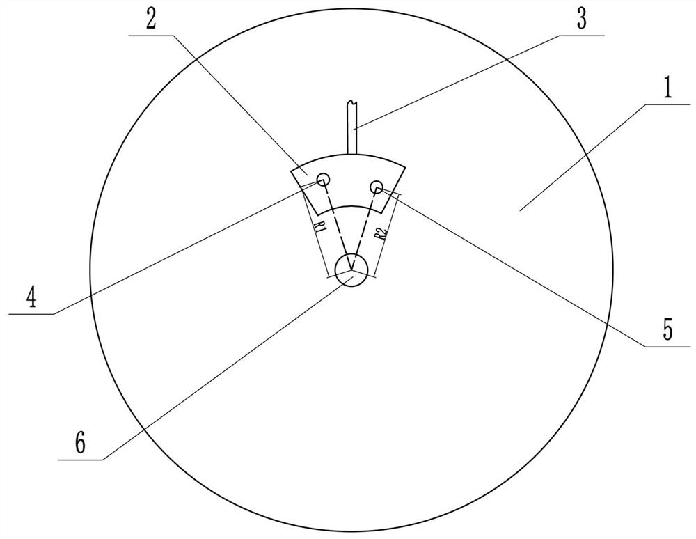
[0008]As attachedfigure 1As shown, the present invention includes a reagent tray 1, a liquid addition tank 2 arranged on the reagent tray 1, and a liquid outlet pipe 3 connected with the liquid addition tank 2. The liquid outlet pipe 3 shown is connected with the subsequent functional area to connect The liquid sample in the liquid addition tank 2 is transported for subsequent processing. The reagent disc 1 has a rotating shaft 6, and the centrifugal force is generated by the rotation of the reagent disc 1 to realize liquid transfer.

[0009]In the present invention, there are two holes on the liquid adding tank 2, namely the exhaust hole 4 and the sample hole 5. The distance between the air exhaust hole 4 and the rotation axis of the reagent disc 1 is R1, and the sample hole The distance between 5 and the axis of rotation of the reagent disc 1 is R2, R2≤R1, so that when the sample is added from the sample hole 5 and the centrifugal operation is performed, the compression hole in the d...


PUM


Abstract

The invention relates to a reagent disc liquid sample adding structure which comprises a reagent disc body, a liquid adding pool arranged on the reagent disc body, a sample adding hole and an exhausthole, the sample adding hole and the exhaust hole are formed in the liquid adding pool, and the distance between the sample adding hole and the rotating center of the reagent disc is smaller than or equal to the distance between the exhaust hole and the rotating center of the reagent disc; the two holes are designed in the liquid adding pool, one hole serves as the sample adding hole, the other hole serves as the exhaust hole, and the sample adding hole is close to the inside in the radial direction relative to the exhaust hole, so that when the reagent disc rotates to enable liquid to move centrifugally, compressed air in the liquid adding pool can be exhausted from the exhaust hole, and liquid splashing caused by overlarge pressure is avoided.

Description

Technical field[0001]The invention relates to a liquid sample loading structure of a reagent disk.Background technique[0002]As a development trend of modern medical treatment, reagent trays are increasingly valued by more companies. The reagent tray can be used to divide the added liquid sample into multiple parts, and a specific pipeline structure can be used to achieve various functions such as sample quantification. However, in the current flow channel structure of the reagent tray, after adding liquid samples, air is compressed during centrifugal movement, and the gas will move toward the centrifugal axis, which may cause splashing at the filling port.Summary of the invention[0003]The technical problem to be solved by the present invention is to provide a reagent disk liquid sample adding structure, which can avoid the situation of liquid splashing.[0004]The technical scheme adopted by the present invention is: a reagent disk liquid sample adding structure, which includes a reag...

Claims


Application Information

Patent Timeline
Patent Type & Authority Applications(China)
IPC IPC(8): G01N35/10
CPCG01N35/10
Inventor 郝书顺陈立柱
Owner SHIJIAZHUANG HIPRO BIOTECH
Why Eureka
Try Eureka