Clutch structure for windlass

A windlass and reel technology, applied in the direction of anchoring/lashing, ship parts, ships, etc., can solve the problems of poor stability, low efficiency, high safety and stability requirements, etc., to enhance stability and improve practicality sexual effect

Pending Publication Date: 2021-08-17
中山市三角镇巨力精密机械制造厂
View PDF0 Cites 0 Cited by
  • Summary
  • Abstract
  • Description
  • Claims
  • Application Information

AI Technical Summary

Problems solved by technology

[0002] With the development of shipping, the windlass is an indispensable device for ships. It is not only used for anchoring, but also an important tool for ship towing. Therefore, windlass generally has multiple drums to achieve more functions. Due to the large force during anchoring or towing, the requirements for safety and stability are high, and the practical efficiency of the windlass also needs to be taken into account; while the existing multi-drum windlass has a relatively poor control structure for independently controlling the work of different drums. Complex, poor stability, low efficiency and high failure rate

Method used


Image

  • Clutch structure for windlass
  • Clutch structure for windlass
  • Clutch structure for windlass

Examples


Embodiment Construction

[0033] The invention provides a clutch structure for a windlass, which is suitable for the field of ship windlasses. The present invention can be implemented in the following ways:

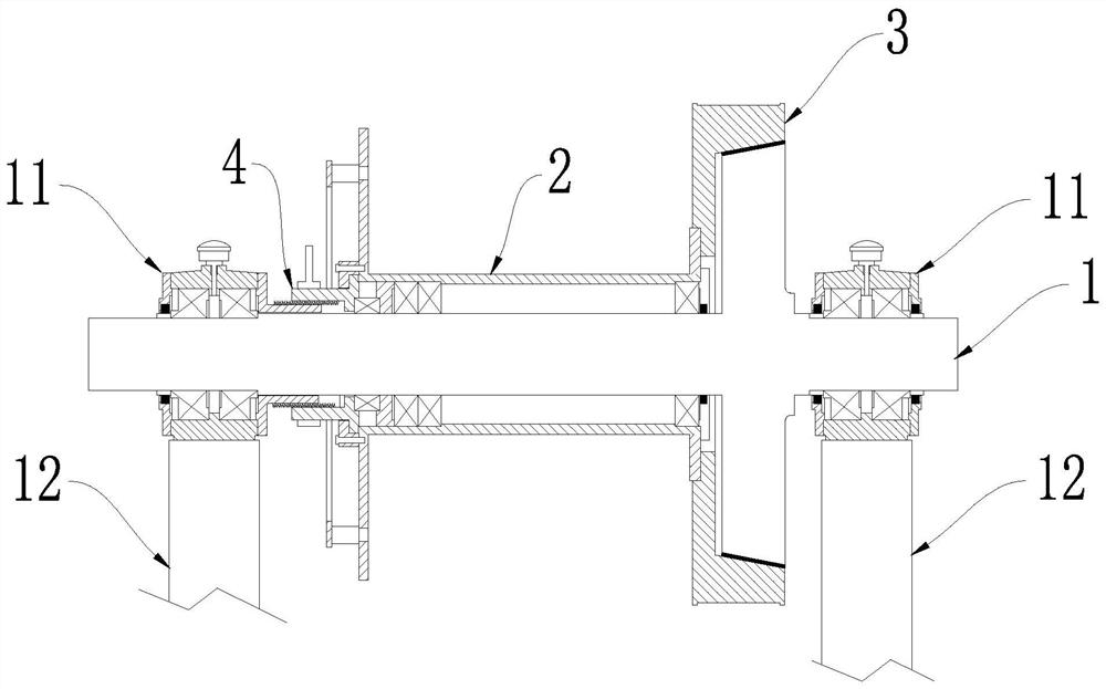
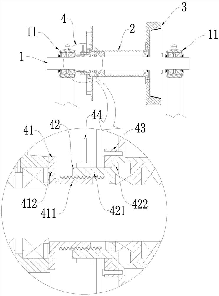
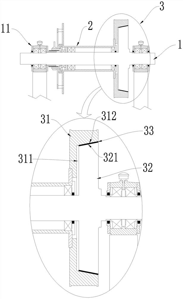
[0034] like Figure 1-17 As shown: the main functional structure of the windlass includes a main shaft 1, a reel 2, and the reel 2 is used to wind cables or chains, etc. The main shaft 1 is connected to the power structure and rotates under the drive of the power structure. Therefore, the main shaft 1 is the power main shaft. The reel 2 is set on the main shaft 1 and rotates under the control of the main shaft 1 to pull the cable; 1 Flexible connection, that is, independent rotation between the reel 2 and the main shaft 1, the reel 2 can slide axially on the main shaft 1, but there is a clutch structure 3 and a clutch between the reel 2 and the main shaft 1 to control the rotation of the reel 2 control structure4.

[0035] like figure 1 , 3 -As shown in 4, 6, 7, 14-17: the clutch structure 3 ...


PUM


Abstract

The invention relates to the field of ship cablelifter, and provides a clutch structure for a cablelifter. According to the technical scheme, a body comprises a main shaft and a winding drum, the main shaft is connected with an inner cone pulley synchronously rotating with the main shaft, one end of the winding drum is fixedly connected with an outer cone pulley synchronously rotating with the winding drum, and the inner cone pulley is matched with the outer cone pulley; according to the scheme, the stability of the clutch structure of the cablelifter is enhanced, and the practicability, the safety and the working efficiency of the cablelifter are improved.

Description

technical field [0001] The invention relates to the field of ship windlasses, in particular to a clutch structure for windlasses. Background technique [0002] With the development of shipping, the windlass is an indispensable device for ships. It is not only used for anchoring, but also as an important tool for ship towing. Therefore, the windlass generally has multiple drums to achieve more functions. Due to the large force during anchoring or towing, the requirements for safety and stability are high, and the practical efficiency of the windlass also needs to be taken into account; while the existing multi-drum windlass has a relatively poor control structure for independently controlling the work of different drums. Complex, poor stability, low efficiency and high failure rate. Contents of the invention [0003] The invention provides a clutch structure for a windlass, the purpose of which is to enhance the stability of the clutch structure of the windlass and improve...

Claims


Application Information

Patent Timeline
IPC IPC(8): B63B21/22B63B21/04
CPCB63B21/04B63B21/22B63B2205/04B63B2205/06
Inventor 吴志标
Owner 中山市三角镇巨力精密机械制造厂
Why Eureka
Try Eureka