Supercharge Your Innovation With Domain-Expert AI Agents!

Reaction cup washing mechanism and reaction cup washing method

A technology for cuvettes and cup holes, which is applied in separation methods, cleaning methods and utensils, chemical instruments and methods, etc., and can solve the problems of easy carryover pollution, low cleaning efficiency of cuvettes, and large loss of tips, etc.

Pending Publication Date: 2021-08-20
宙斯生命科技(常州)有限公司
View PDF0 Cites 2 Cited by
  • Summary
  • Abstract
  • Description
  • Claims
  • Application Information

AI Technical Summary

Problems solved by technology

[0007] The technical problem to be solved by the present invention is to overcome the deficiencies of the prior art, provide a cuvette washing mechanism and a cuvette washing method, and solve the problems of easy carryover of cuvette washing, large loss of tips and low cleaning efficiency of cuvettes The problem

Method used


Image

  • Reaction cup washing mechanism and reaction cup washing method
  • Reaction cup washing mechanism and reaction cup washing method
  • Reaction cup washing mechanism and reaction cup washing method

Examples


Embodiment 1

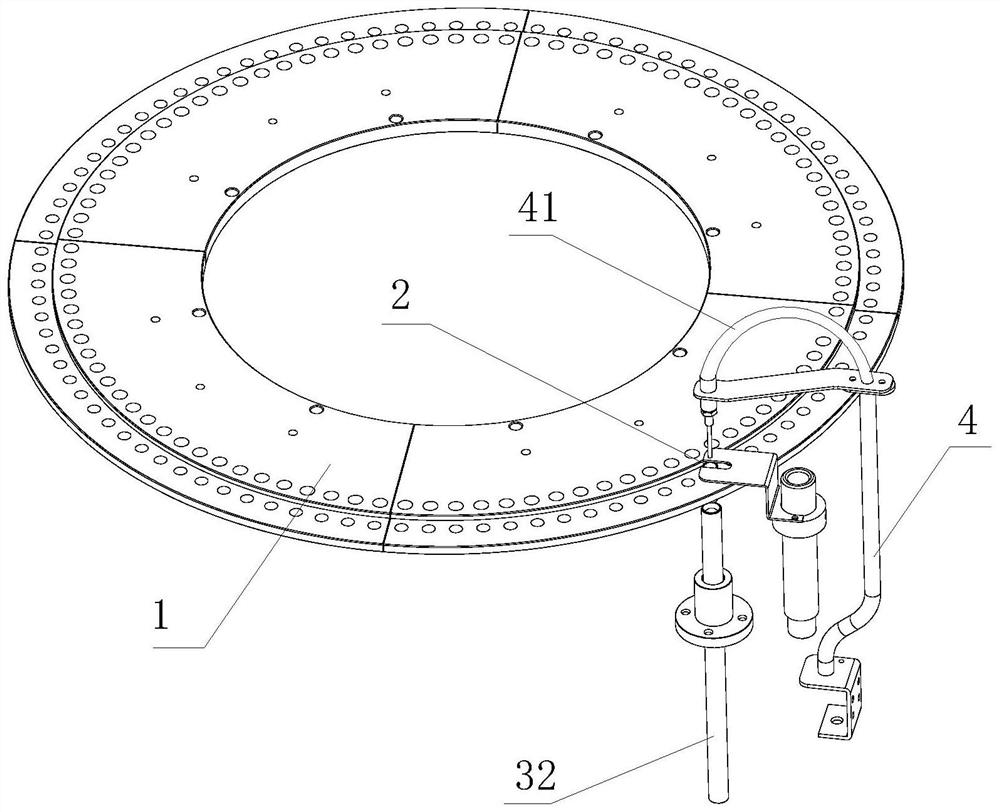
[0044] like Figure 1 to Figure 4 As shown, a cuvette washing mechanism includes an operating table, on which a cup and tray 1 is arranged, and the cup and tray 1 are moved and set on the operating table; a plurality of cup placement holes are provided on the cup and tray 1, The cuvette 2 is placed in the cup hole;

[0045] Reaction cup 2, the upper end of the reaction cup 2 is provided with a liquid inlet, and the bottom is provided with a liquid discharge port. The liquid discharge port is provided with a filter membrane 23. When the liquid discharge port is at normal pressure, the filter membrane 23 is suitable for supporting the reaction Sample reaction solution in cup 2;

[0046] A liquid discharge mechanism 3, when the cuvette 2 moves to the liquid discharge station of the console, the liquid discharge mechanism 3 is in sealing connection with the liquid discharge port at the bottom of the cuvette 2, and provides negative pressure to the liquid discharge port to Drain ...

Embodiment 2

[0064] A method for washing cuvettes, using the cuvette 2 washing mechanism of Embodiment 1, comprising the following steps:

[0065] Step S01, the cuvette 2 is filled with a mixture of the sample and the microsphere reagent, and the cuvette 2 moves on the operating table along with the cup and tray 1;

[0066] When the cuvette 2 moves to the liquid discharge station, at this time, the cuvette 2 is located below the baffle 34;

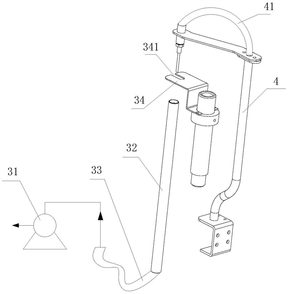
[0067] Step S02, the push-pull electromagnet drives the hard tube 32 to move upward until the upper end of the hard tube 32 forms a sealing fit with the liquid discharge port at the bottom of the cuvette 2, and then the negative pressure pump 31 works to remove the mixed liquid in the cuvette 2, The filter membrane 23 keeps the microsphere sieve in the mixed solution in the cuvette 2;

[0068] Step S03, then fill the cuvette 2 with cleaning solution through the liquid filling pipe 41, and clean the microspheres through the cleaning solution. After the...


PUM


Abstract

The invention relates to a reaction cup washing mechanism which comprises an operation table, a cup plate is arranged on the operation table, and a reaction cup is placed in a cup placing hole. The bottom of the reaction cup is provided with a liquid outlet provided with a filter membrane. When the reaction cup is moved to a liquid discharging station of the operation table, a liquid discharging mechanism discharges sample reaction liquid in the reaction cup. A reaction cup washing method comprises the following steps that the reaction cup is filled with mixed liquid of a sample and a microsphere reagent, and the reaction cup moves on the operation table along with the cup plate; the reaction cup is moved to the liquid discharging station; a negative pressure pump works to remove the mixed liquid in the reaction cup, and microspheres in the mixed liquid are sieved in the reaction cup by the filter membrane; and then, cleaning liquid is injected into the reaction cup through a liquid adding pipe, the cleaning liquid is removed through the negative pressure pump, and the operation is repeated for multiple times till the microspheres are cleaned up. Carrying of pollutants in the test process is avoided, the tip head loss is reduced, and the washing efficiency of the reaction cup is improved.

Description

technical field [0001] The invention relates to the field of tubular light-emitting systems, in particular to a reaction cup washing mechanism and a reaction cup washing method. Background technique [0002] During the analysis process of the tube-type luminescence test, the diluted sample and the microsphere reagent (the microsphere is a magnetic microsphere) are mixed in the reaction cup to form a mixed solution; the sample reacts in the reagent, and the reaction substance is attached to the microsphere carrier. After the reaction is completed, the cuvette needs to be washed. The purpose of washing is to remove the liquid other than the microspheres, and then inject the washing liquid to wash the microspheres several times. After the microspheres are cleaned, another reagent is injected to carry out chemical reaction. In the luminescence test, the more reactive substances attached to the magnetic microspheres, the brighter the light emitted. [0003] The existing tube-typ...

Claims


Application Information

Patent Timeline
Patent Type & Authority Applications(China)
IPC IPC(8): B08B9/08B08B13/00B01D29/05B01J19/00B01D61/00
CPCB08B9/0821B08B9/08B08B13/00B01D29/05B01D61/00B01J19/0053
Inventor 宣生良
Owner 宙斯生命科技(常州)有限公司
Features
  • R&D
  • Intellectual Property
  • Life Sciences
  • Materials
  • Tech Scout
  • Unparalleled Data Quality
  • Higher Quality Content
  • 60% Fewer Hallucinations
Learn More