
Electric power tool storage scaffold

A technology for power tools and construction racks, which is applied to tool storage devices, manufacturing tools, etc., can solve the problems of inconvenient storage, inconvenience of folding, and inconvenience in carrying, and achieves the effect of reducing the space occupied by the area, facilitating the wiring operation, and being easy to carry.

Pending Publication Date: 2021-08-20
GUANGDONG POWER GRID CO LTD +1
View PDF7 Cites 0 Cited by
  • Summary
  • Abstract
  • Description
  • Claims
  • Application Information

AI Technical Summary

Problems solved by technology

[0002] In the construction process of electric power engineering, it is often necessary to pay out the cables on the reel, and the existing power tool storage construction rack only plays the role of storing power tools, and does not have the function of reeling out the wire reel. An additional pay-off stand is required on site for the pay-off operation. The pay-off stand is bulky and inconvenient to carry, which brings a burden to the on-site operations.
In addition, the existing hook rack for storing construction racks for electric tools is directly fixed on the main body of the construction rack and cannot be folded at will. During the storage process, the opened hook rack takes up a large space and is inconvenient to store.

Method used


Image

  • Electric power tool storage scaffold
  • Electric power tool storage scaffold
  • Electric power tool storage scaffold

Examples


Embodiment 1

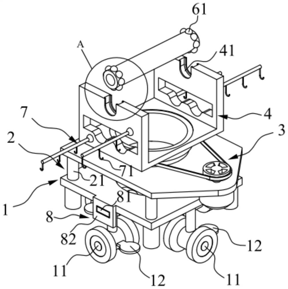
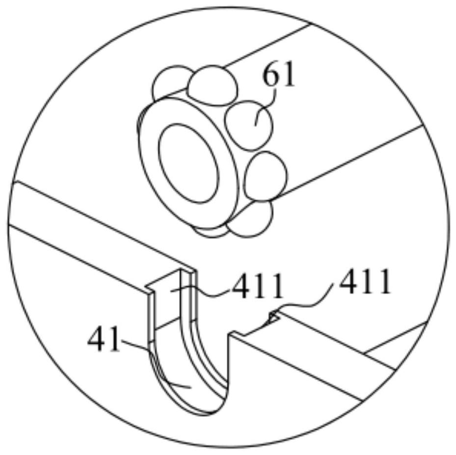
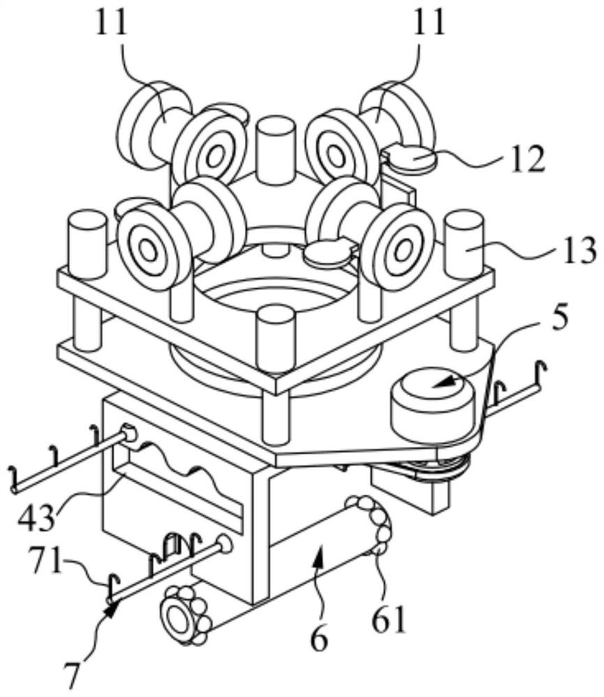
[0041] Such as Figure 1-Figure 4 As shown, the present invention provides a power tool storage construction frame, including a base 1, a lifting mechanism 2, a mounting seat 3, a support frame 4, a driving device 5, a pay-off shaft 6 and a plurality of hanging rods 7, the lifting mechanism 2 One end is fixedly connected with the base 1; the mounting base 3 is fixedly installed on the other end of the lifting mechanism 2, and the lifting mechanism 2 can drive the mounting base 3 to lift in the vertical direction; the support frame 4 is rotatably installed on the mounting base 3, and the support frame 4 is set There are two supporting grooves 41; the driving device 5 is fixedly installed on the mounting base 3, and the driving device 5 is configured to drive the supporting frame 4 to rotate; Rotation connection (in the accompanying drawings, the structure of the pay-off shaft 6 is shown, so that the pay-off shaft 6 is separated from the support groove 41); In this embodiment, ...

Embodiment 2

[0050] This embodiment is further improved on the basis of embodiment one, as figure 1 As shown, it also includes an integrated control module 8, the integrated control module 8 includes a single-chip microcomputer 81, the single-chip microcomputer 81 is installed on the side of the base 1, and the single-chip microcomputer 81 is connected with the lifting mechanism 2 and the driving device 5 respectively, and can control the lifting mechanism 2 lifting operations , Control and start the driving device 5 to drive the support frame 4 to rotate. In addition, the integrated control module 8 also includes a wireless transceiver 82, which is used for remote interaction of information, and the single-chip microcomputer 81 communicates with the lifting mechanism 2 and the driving device 5 through the wireless transceiver 82 to ensure smooth operation. Convenience and intelligence.


PUM


Abstract

The invention belongs to the technical field of electric power tool storage, and discloses an electric power tool storage scaffold which comprises a base, a lifting mechanism, a mounting seat, a supporting frame, a driving device, a pay-off shaft and a plurality of hanging rods. One end of the lifting mechanism is fixedly connected with the base; the mounting seat is fixedly mounted at the other end of the lifting mechanism, and the lifting mechanism can drive the mounting seat to ascend and descend in the vertical direction; the supporting frame is rotatably mounted on the mounting seat, and two supporting grooves are formed in the supporting frame; the driving device is fixedly mounted on the mounting seat, and the driving device is configured to drive the supporting frame to rotate; the pay-off shaft is erected on the two supporting grooves and rotatably connected with the two supporting grooves; and the hanging rods are rotatably connected with the supporting frame. According to the electric power tool storage scaffold, through cooperation of the lifting mechanism and the driving device, the working height and angle of the pay-off shaft and the hanging rods can be adjusted, the pay-off shaft and the hanging rods are made to be arranged at the optimal positions, and operators can conduct pay-off operation and take electric power tools conveniently.

Description

technical field [0001] The invention relates to the technical field of power tool storage, in particular to a power tool storage construction frame. Background technique [0002] In the construction process of electric power engineering, it is often necessary to pay out the cables on the reel, and the existing power tool storage construction rack only plays the role of storing power tools, and does not have the function of reeling out the wire reel. It is necessary to prepare another pay-off rack on site for the pay-off operation. The overall pay-off rack is heavy and inconvenient to carry, which brings a burden to the on-site operation. In addition, the existing hook rack for storing construction racks for electric tools is directly fixed on the main body of the construction rack and cannot be folded arbitrarily. Contents of the invention [0003] The purpose of the present invention is to provide a power tool storage construction frame, which can adjust the working heig...

Claims


Application Information

Patent Timeline
Patent Type & Authority Applications(China)
IPC IPC(8): B25H3/04
CPCB25H3/04
Inventor 黄淑芬陈清华蓝超陈军华陈嘉紫何维黄威刘文秀曾伟欢朱伟海
Owner GUANGDONG POWER GRID CO LTD
Learn More