Sleeper type internal locking electro-hydraulic conversion equipment

An electro-hydraulic conversion and locking technology, which is applied in the direction of hydraulic equipment for manipulating turnouts or circuit breakers, locking mechanisms for turnouts, railway signals, etc., can solve inconvenience, be easily limited by space, and reduce turnout sections Track dynamic performance and other issues, to achieve the effect of simple and flexible installation, reduce internal damage, and improve track dynamic performance

Pending Publication Date: 2021-08-20
TAIYUAN JINGFENG RAILWAY EQUIP MANUFCTURING CO LTD +1
View PDF0 Cites 0 Cited by
  • Summary
  • Abstract
  • Description
  • Claims
  • Application Information

AI Technical Summary

Problems solved by technology

[0002] At present, the internal locking electro-hydraulic conversion equipment generally adopts the side-mounted type, that is, the switch machine, the conversion locker and the hydraulic station are all installed outside the basic rail of the turnout; however, this installation method is easily limited by space. For narrow spaces, such as Bridges and tunnels, etc., the side-mounted internal locking electro-hydraulic conversion is obviously inconvenient, which greatly reduces the track dynamic performance of the turnout section

Method used


Image

  • Sleeper type internal locking electro-hydraulic conversion equipment
  • Sleeper type internal locking electro-hydraulic conversion equipment
  • Sleeper type internal locking electro-hydraulic conversion equipment

Examples


Embodiment Construction

[0027] Exemplary embodiments of the present invention will be described in more detail below with reference to the accompanying drawings. Although exemplary embodiments of the present invention are shown in the drawings, it should be understood that the invention may be embodied in various forms and should not be limited to the embodiments set forth herein. Rather, these embodiments are provided for more thorough understanding of the present invention and to fully convey the scope of the present invention to those skilled in the art.

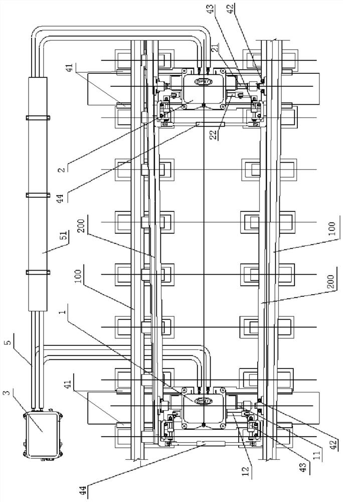
[0028] Such as figure 1 As shown, the present invention provides a sleeper-type internal locking electro-hydraulic conversion equipment for switch conversion, locking, and position indication; it includes a switch machine 1, a conversion locker 2, a hydraulic station 3 and an installation device; wherein Switch machine 1 is preferably ZYJG7 type internal locking sleeper type switch machine; conversion locker 2 is preferably SHG6 internal lockin...


PUM


Abstract

The invention discloses a sleeper type internal locking electro-hydraulic conversion equipment comprises a switch machine, a conversion locking device, a hydraulic station and a mounting device, the point switch and the switching locker are respectively arranged at a first traction point and a second traction point between the two stock rails; the hydraulic station is mounted on the outer side of the stock rail and is connected with the point switch and the conversion locker through oil pipes; the mounting device comprises basic angle steel, an action mechanism, an indication mechanism and a tip rod. The point switch and the switching locker are respectively connected with the stock rail through the basic angle steel; the two ends of an actuating rod of the switch machine and the two ends of an actuating rod of the switching locker can push an actuating mechanism connected with the switch rail, and turnout switching is achieved. The two ends of a locking rod of the switch machine and the two ends of an indication rod of the switching locker are connected with the switch rails on the two sides through indication mechanisms respectively, and the indication mechanisms can feed back the positions of the switch rails. The tip rod is connected with the two switch rails and keeps the two switch rails to act in the same direction. The device is convenient and flexible to install, especially suitable for installation in a narrow space and easy to maintain.

Description

technical field [0001] The invention relates to the field of turnout switching equipment, in particular to a sleeper-type internal locking electro-hydraulic switching equipment. Background technique [0002] At present, the internal locking electro-hydraulic conversion equipment generally adopts the side-mounted type, that is, the switch machine, the conversion locker and the hydraulic station are all installed outside the basic rail of the turnout; however, this installation method is easily limited by space. For narrow spaces, such as For bridges and tunnels, etc., this kind of side-mounted internal locking electro-hydraulic conversion is obviously inconvenient, which greatly reduces the track dynamic performance of the turnout section. Contents of the invention [0003] The technical problem to be solved by the present invention is to provide a sleeper-type internal locking electro-hydraulic conversion device which is easy and flexible to install, especially suitable fo...

Claims


Application Information

Patent Timeline
IPC IPC(8): B61L5/04B61L5/10
CPCB61L5/045B61L5/10
Inventor 赵永根张郁徐建军张伟闫瑞康王历珘施聪黄晓荣吴杰颜韵飞戴洋竞柳笑卫
Owner TAIYUAN JINGFENG RAILWAY EQUIP MANUFCTURING CO LTD
Why Eureka
Try Eureka